Process for repairing metallic pieces especially turbine blades of a gas turbine motor

a technology of gas turbine blades and metal parts, which is applied in the direction of turbines, machines/engines, manufacturing tools, etc., can solve the problems that the contact zone cannot be prevented from being altered, and achieve the effect of preventing cracks

Active Publication Date: 2009-03-31
SN DETUDE & DE CONSTR DE MOTEURS DAVIATION S N E C M A
View PDF25 Cites 15 Cited by
  • Summary
  • Abstract
  • Description
  • Claims
  • Application Information

AI Technical Summary

Benefits of technology

[0015]The process also applies both to a mobile blade and to a stator vane. In particular, it applies to a mobile turbine blade with shroud, whereof the shroud is in a Z profile and comprises a pit at the base of the profile. Such a pit consists of a bore with a rounded profile in the re-entrant zone of the Z. Its aim is to prevent development of cracks in this zone.
[0016]According to another characteristic, with the process being applied to a shroud blade w

Problems solved by technology

In spite of the protection conferred by the anti-wear layer, the contact zones cann

Method used


Image

  • Process for repairing metallic pieces especially turbine blades of a gas turbine motor
  • Process for repairing metallic pieces especially turbine blades of a gas turbine motor
  • Process for repairing metallic pieces especially turbine blades of a gas turbine motor

Examples


Embodiment Construction

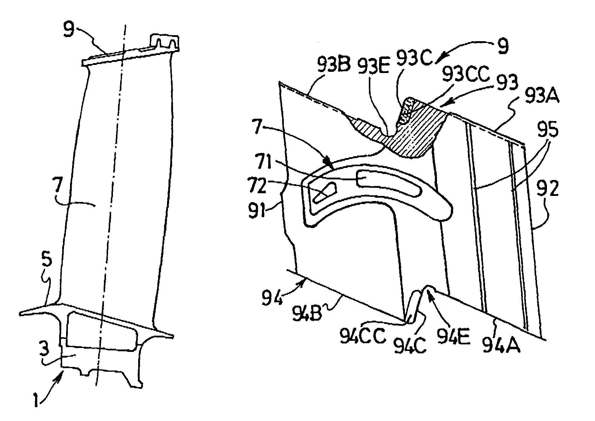
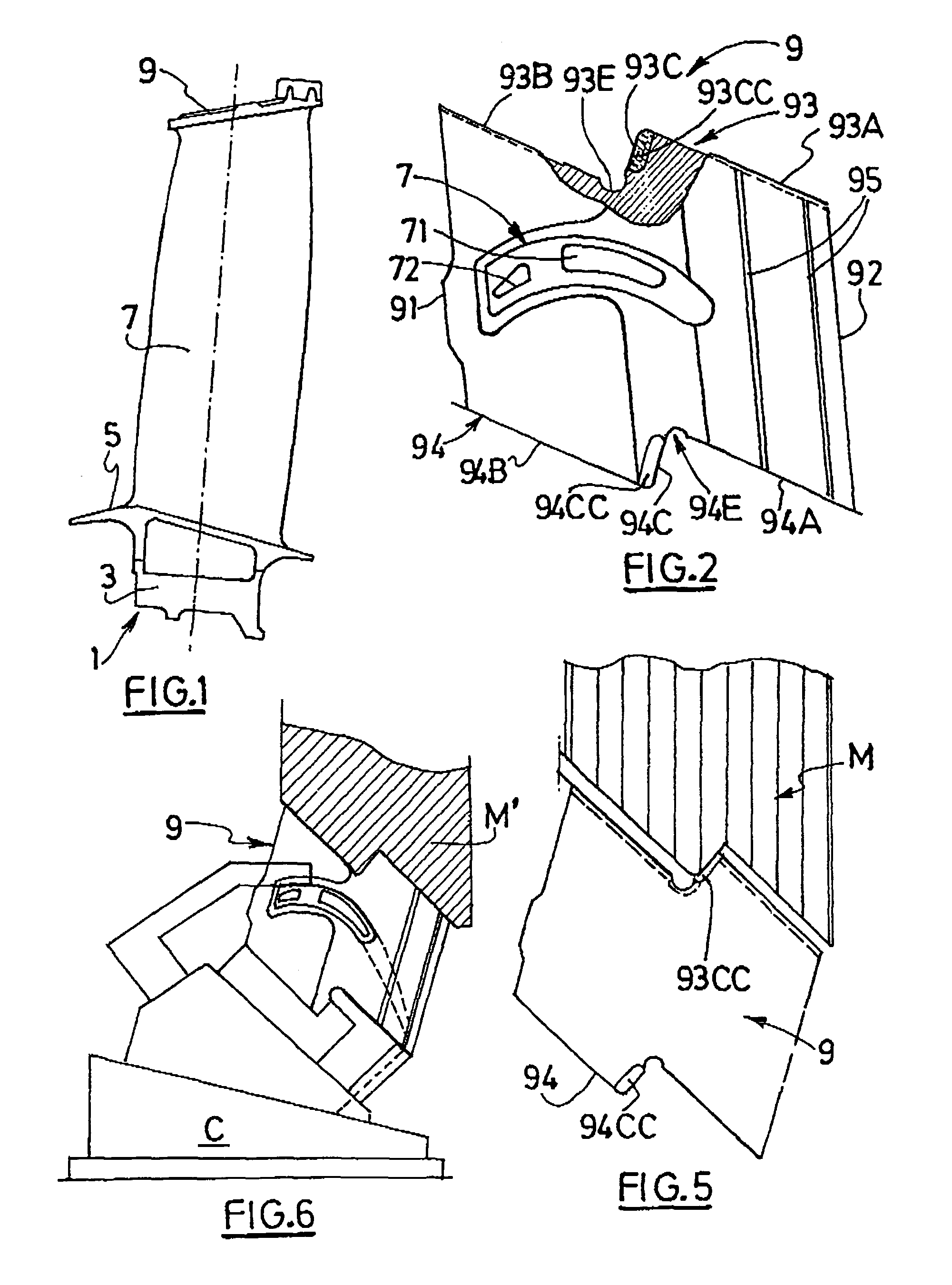
[0029]FIGS. 1 and 2 illustrate a turbine blade utilised in a high-pressure stage of a motor subjected to extreme conditions, such as for example a military engine. This blade comprises a root portion 3, a platform 5 forming an element of the internal wall delimiting the gas vein which passes through the turbine and the aerofoil portion 7 which is swept by the gas. The aerofoil portion 7 is united at the radially outer tip with a shroud 9, forming an element of the external wall delimiting the gas vein which passes through the turbine stage on which the blade is mounted. FIG. 2 shows the shroud 9 in plan view.

[0030]In this model the shroud, having a general parallelepiped shape, comprises an upstream face 91 perpendicular to the gaseous flux, a downstream face 92 which is parallel to the former, and two lateral faces 93 and 94 which connect the two preceding. This figure also shows the upper end the aerofoil portion 7 with its vents 71, 72 for cooling fluid which has passed through t...


PUM

PropertyMeasurementUnit
Lengthaaaaaaaaaa
Thicknessaaaaaaaaaa
Pressureaaaaaaaaaa

Abstract

A process for repairing a metallic shroud of a gas turbine blade includes a step of removing a portion of an anti-wear layer to a removal depth that is greater than a depth of wear of the anti-wear layer. Further, the process includes a step of leaving a trace of the anti-wear layer to subsist, wherein the trace of the anti-wear layer extends at least in a re-entrant zone of the Z profile of the blade. The process also includes a step of depositing a new layer of anti-wear material on the trace of the anti-wear layer.

Description

BACKGROUND OF THE INVENTION[0001]1. Field of the Invention[0002]The present invention concerns metallic pieces and especially gas turbine blades. In particular, it focuses on repair of the parts of blades which are coated with a layer of an anti-wear material for resisting constraints due to major friction during operation of the motor. The repair process applies to the mobile rotor blades or fixed stator vanes.[0003]2. Discussion of the Background[0004]A mobile turbine blade comprises a root portion by which it is fixed to the disc of the rotor, a platform delimiting the gas vein and an aerofoil portion. According to the motor and the turbine stage, the aerofoil portion terminates, at its end remote from the root, in a transversal element, known as a shroud, which delimits the external surface of the gas vein. The shroud comprises a leading edge and a trailing edge oriented transversally relative to the direction of flow of the gas. The two edges are connected by two lateral edges ...

Claims


Application Information

Patent Timeline
IPC IPC(8): B23P6/00B23K9/04F01D5/00
CPCB23K9/044B23P6/007F01D5/005B23K2201/001Y10T29/49746Y10T29/49726Y10T29/49725Y10T29/49728Y10T29/49748Y10T29/49318Y10T29/49732B23K2101/001
Inventor BOUDEREAU, CHRISTIANBOULNOIS, MICHELBOUSSABOUN, HASSANCARUANA, CHARLESCAUX, JEAN-MARCCHAREYRE, FRANCISDEFROCOURT, GERARDHERAULT, PATRICKSAMPAIO, CLEMENTVARIN, JEAN-JACQUES
Owner SN DETUDE & DE CONSTR DE MOTEURS DAVIATION S N E C M A
Why Eureka
Try Eureka