A beam bridge reinforcement structure and reinforcement method

A reinforced structure and beam-type technology, applied in bridge reinforcement, bridge, bridge maintenance, etc., can solve problems such as difficult to guarantee bearing capacity requirements and service life, unfavorable projects widely popularized and applied, and large amount of reinforcement projects, etc., to achieve reduction in constant Load and live load bending moment force effect, reduce load burden and operation risk, reduce the effect of burden

Active Publication Date: 2018-04-24
JIANGSU UNIV OF SCI & TECH
View PDF6 Cites 0 Cited by
  • Summary
  • Abstract
  • Description
  • Claims
  • Application Information

AI Technical Summary

Problems solved by technology

The disadvantage of this cable-stayed reinforcement method and technology is that it is necessary to build additional tower columns together with pile foundations, and to build additional cover beams and widened sections of box girders, which requires a large amount of reinforcement work and a long period of time It is long, and involves the anchoring and tensioning of the cables, and the construction process is complicated, which is not conducive to the widespread application of the project
[0004] Therefore, for existing girder bridges, conventional reinforcement methods cannot solve the problem of excessive stress, and it is difficult to ensure the requirements of its bearing capacity and service life. It is necessary to study reinforcement methods that are cost-effective and effective

Method used


Image

  • A beam bridge reinforcement structure and reinforcement method
  • A beam bridge reinforcement structure and reinforcement method
  • A beam bridge reinforcement structure and reinforcement method

Examples


Embodiment Construction

[0027] The present invention will be further described below in conjunction with the accompanying drawings and specific embodiments, but the protection scope of the present invention is not limited thereto.

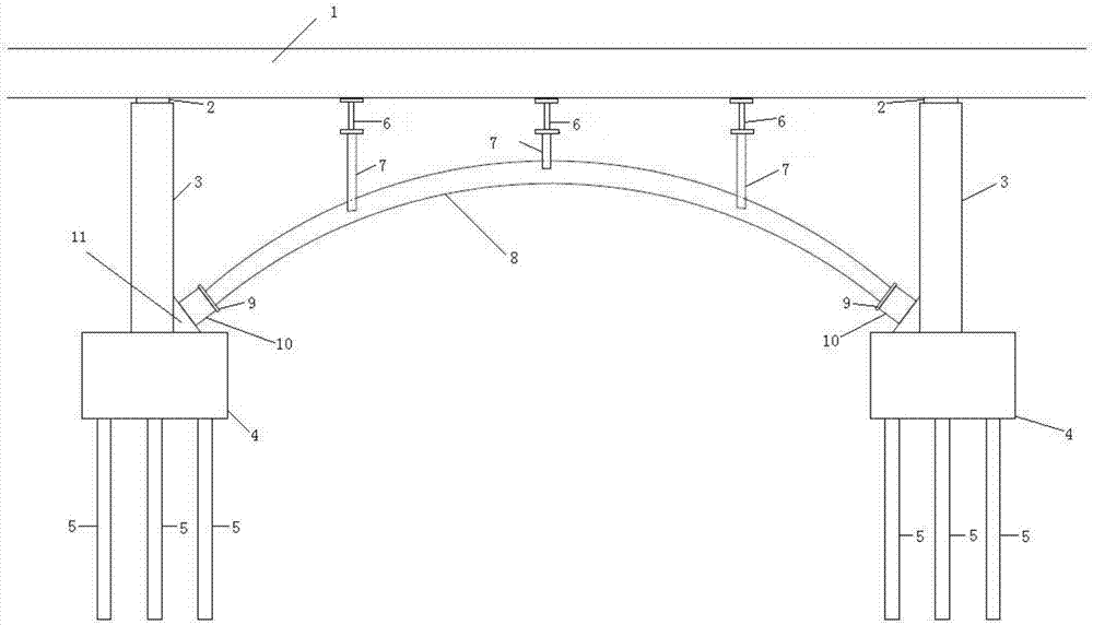
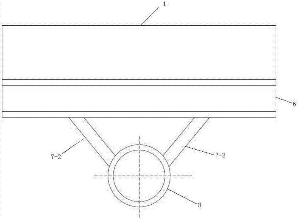
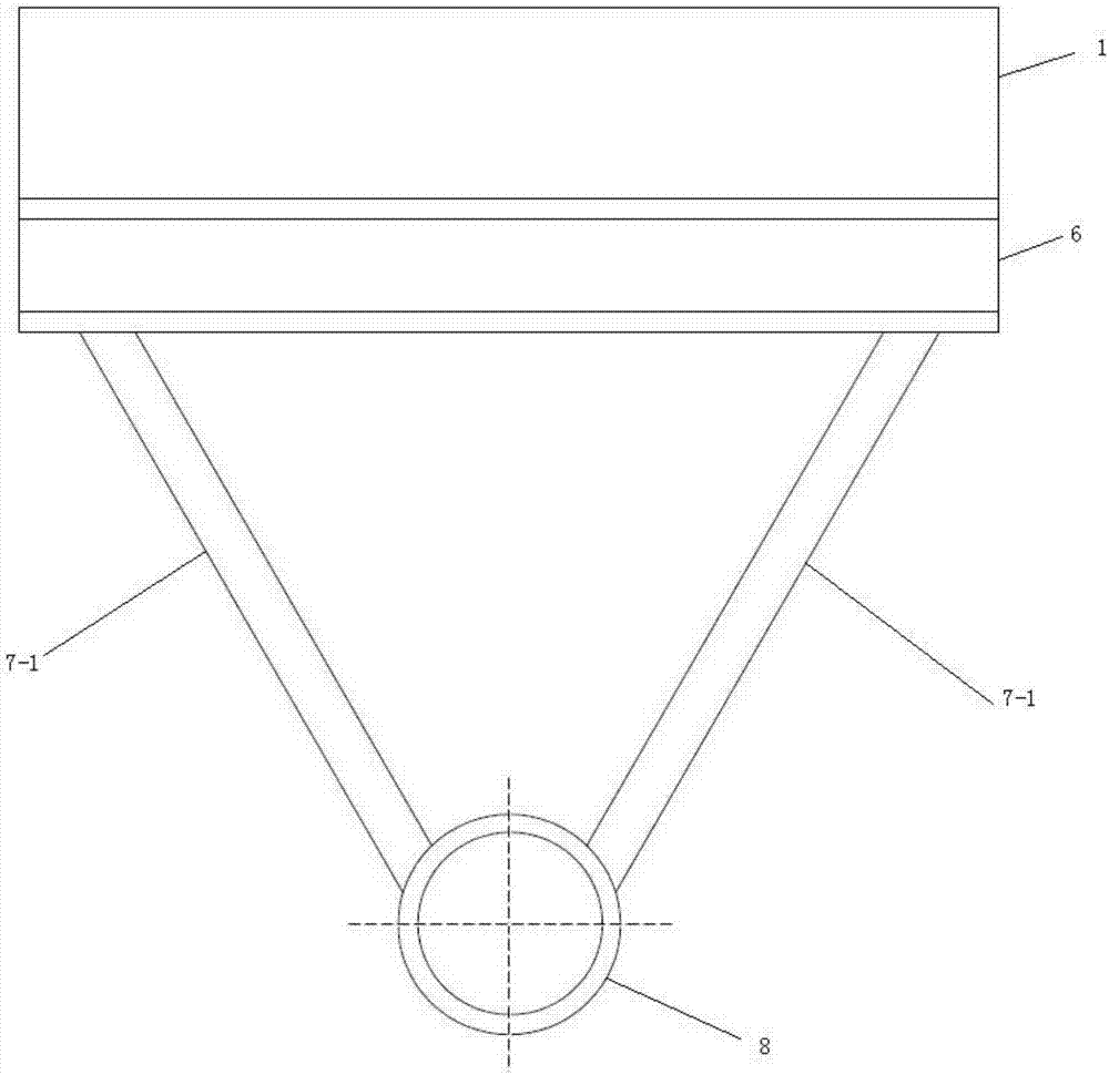
[0028] A girder bridge reinforcement structure, comprising an arched steel pipe member 8, an I-shaped steel 6 and a steel diagonal brace 7; the two ends of the arched steel pipe member 8 are fixed to two adjacent piers 3 of the bridge body; the arched steel pipe member The middle section of 8 is fixedly connected with the steel diagonal brace 7, and the steel diagonal brace 7 is fixedly connected with the I-beam 6; the I-beam 6 is fixedly installed on the upper beam of the bridge body; the steel diagonal The support 7 includes a left diagonal brace 7-1 and a right diagonal brace 7-2, one end of the left diagonal brace 7-1 and the right diagonal brace 7-2 is fixedly connected with the arched steel pipe member 8, and the other end is connected with the I-beam 6 fixed connec...


PUM


Abstract

The invention provides a girder bridge reinforcement structure and reinforcement method, comprising an arched steel pipe member, I-shaped steel and steel diagonal braces, the two ends of the arched steel pipe member are fixed on two adjacent piers of the bridge body, and the arched The middle section of the steel pipe member is fixedly connected with the steel diagonal brace, and the steel diagonal brace is fixedly connected with the I-beam, and the upper flange of the I-beam provides continuous support for the bottom of the bridge deck of the girder bridge. The reinforcement structure optimizes the stress of the original beam bridge, significantly reduces the bending moment of the beam bridge, effectively prevents the further development of cracks in the beam bridge under the action of overload, and can partially close some cracks and protect the stressed steel bars inside the beam bridge. Avoid exposure and corrosion, significantly reduce the load burden and operational risk of the girder bridge, improve the structural bending and shear bearing capacity and durability of the girder bridge, and effectively prolong the service life of the bridge.

Description

technical field [0001] The invention belongs to the technical field of bridge engineering, and in particular relates to a girder bridge reinforcement structure and a reinforcement method. Background technique [0002] The multi-span simply supported girder bridges, continuous girder bridges, continuous rigid frame bridges, and T-shaped rigid frame bridges built in my country in the early days have been used for a long time. With the development of the economy, the weight of vehicles and traffic flow continue to increase. The original bridge The design load level of the bridge was obviously smaller than the actual vehicle load later, the bridge safety reserve was insufficient, some beam bridges had different degrees of operational damage and disease, different degrees of bridge cracks, steel bar corrosion and excessive deformation of the bridge, resulting in these The bearing capacity of the bridge has declined to varying degrees, and the durability has dropped sharply, which h...

Claims


Application Information

Patent Timeline
Patent Type & Authority Patents(China)
IPC IPC(8): E01D22/00
CPCE01D22/00
Inventor 周道传刘平邵建华王仁华周爱兆董作超潘志宏王林
Owner JIANGSU UNIV OF SCI & TECH
Why Eureka
Try Eureka