
Oxygen-fired front end for glass forming operation

a technology of oxygen-fired front end and glass forming operation, which is applied in glass tempering apparatus, furnaces, lighting and heating apparatus, etc., can solve the problems of low combustion efficiency inefficient operation, and high construction cost of air-gas mixture firing system

Inactive Publication Date: 2009-03-31
OCV INTELLECTUAL CAPITAL LLC
View PDF45 Cites 95 Cited by
  • Summary
  • Abstract
  • Description
  • Claims
  • Application Information

AI Technical Summary

Problems solved by technology

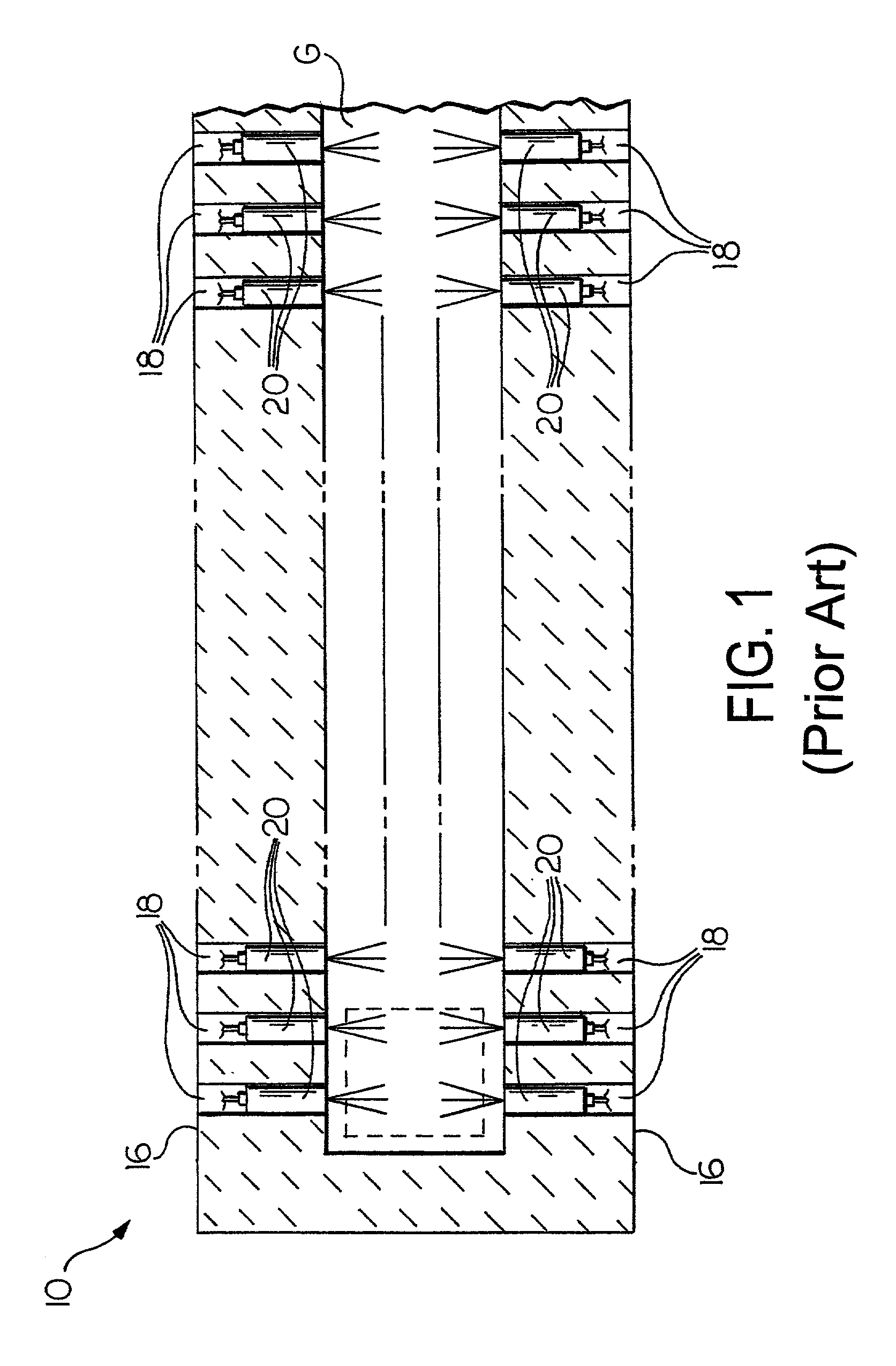
An air-gas mixture firing system is not only costly to construct, it is inefficient to operate.
Thus, an air-gas mixture firing system has minimum efficiency of combustion.
In addition to having a minimum efficiency of combustion, an air-gas mixture firing system is an inefficient means to heat the molten glass G. The flame temperature of an air-gas mixture burner in the air-gas mixture firing system reaches about 3500° F. However, the optical properties of the molten glass G and products of combustion limit the amount of radiant energy that penetrates the molten glass G. This causes the temperature gradient to be high vertically through the molten glass G. The only way to control the temperature distribution is to control the profile of the burners.
Although an oxygen-gas mixture firing system provides uniform glass temperature, it requires an extensive number of complex and costly components.
A conventional oxygen-gas mixture system uses about six oxygen-gas burners per foot, resulting in a cost of about $6,000 per foot.

Method used


Image

  • Oxygen-fired front end for glass forming operation
  • Oxygen-fired front end for glass forming operation
  • Oxygen-fired front end for glass forming operation

Examples


Embodiment Construction

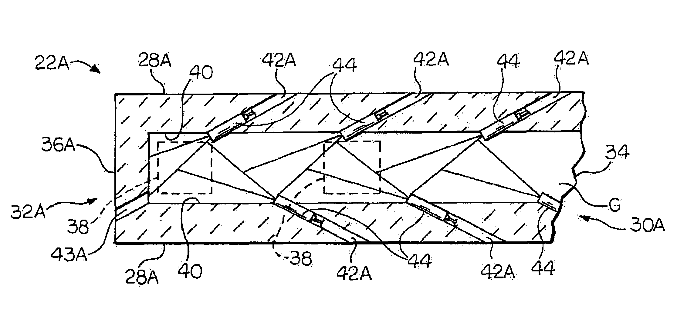
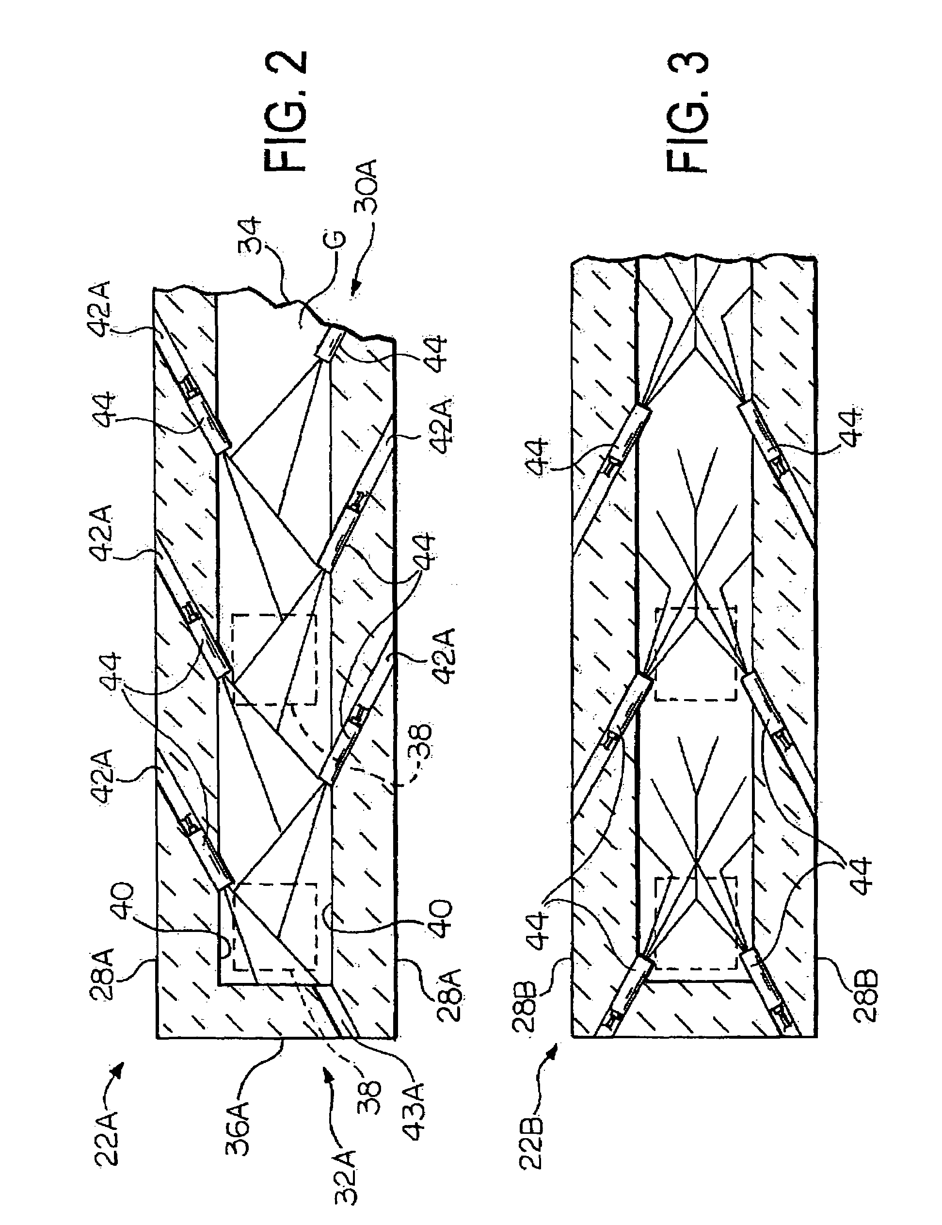
[0022]Referring now to the drawings, there is illustrated in FIG. 2 a front end of a glass forming operation. The front end comprises an open channel and a forehearth downstream of the open channel. To simplify the description, the channel and forehearth will be cooperatively described as a channel 22A. The channel 22A is adapted to deliver molten substance (e.g., molten glass G) from a melter to a point of production (i.e., a forming position). Neither the melter nor the forming position is shown.

[0023]Molten glass G does not contact an upper portion of the channel 22A. That is to say, an upper portion of the channel 22A is above the molten glass level (i.e., the molten glass level L shown in FIGS. 4 and 5). Consequently, this portion can be constructed from relatively inexpensive refractory material (i.e., a super structure refractory material, such as silica, mullite, or other materials that are not required to withstand corrosive effects of molten glass G).

[0024]A lower portion ...


PUM

PropertyMeasurementUnit
Temperatureaaaaaaaaaa
Angleaaaaaaaaaa
Angleaaaaaaaaaa

Abstract

A front end for a glass forming operation comprises an open channel and at least one burner. The channel has at least one surface. The surface has at least one hole therein. The burner is oriented in the hole at an acute angle relative to the surface. In another embodiment of the invention, the channel has a top and a pair of sidewalls each having a surface. At least one hole is in at least one of the surfaces. The hole is at an acute angle relative to at least one surface. The burner is an oxygen-fired burner. In yet another embodiment of the invention, the top and sidewalls each have a super structure surface constructed of refractory material. The channel has an upstream end and a downstream end. At least one of the surfaces has a plurality of holes therein. The burners extend at an acute angle relative to at least one surface and in a plane extending between the upstream end and the downstream end and perpendicular to at least one surface. Oxygen-fired burners extend axially through corresponding holes.

Description

BACKGROUND OF THE INVENTION[0001]This invention relates in general to forming operations and more particularly to a front end for use in forming operations. Most particularly, this invention relates to an oxygen-fired front end for use in glass forming operations.[0002]In a forming operation, batch material is reduced to molten substance (e.g., molten glass) by passing the batch material through a melting furnace, which is commonly referred to as a melter. The molten glass is delivered downstream from the melter through a system of channels and forehearths. This system of channels and forehearths is referred to as a front end. The front end serves as a conduit to deliver the molten glass to one or more production points. The front end also serves to cool and condition the molten glass prior to reaching the production points. These production points are referred to as forming positions. Each forming position includes a bushing for fiber forming operation or a gob cutter for a contain...

Claims


Application Information

Patent Timeline
IPC IPC(8): C03B5/16C03B7/06
CPCC03B7/065Y02P40/50C03B7/096
Inventor BAKER, DAVID J.ADAMS, HARRY P.JIAN, CHRISTOPHER Q.TOTH, WILLIAM W.
Owner OCV INTELLECTUAL CAPITAL LLC
Learn More