
Valve assembly with compliant escutcheon

a technology of valve assembly and escutcheon, which is applied in the direction of mechanical control devices, instruments, couplings, etc., can solve the problems of crooked and/or misalignment of the handle and associated decorative elements, the thickness of the wall is more or less than expected, and the functional and aesthetic problems of mounting the control hardware, etc., to achieve a clean and professional appearance

Active Publication Date: 2009-03-31
KOHLER CO
View PDF28 Cites 34 Cited by
  • Summary
  • Abstract
  • Description
  • Claims
  • Application Information

AI Technical Summary

Benefits of technology

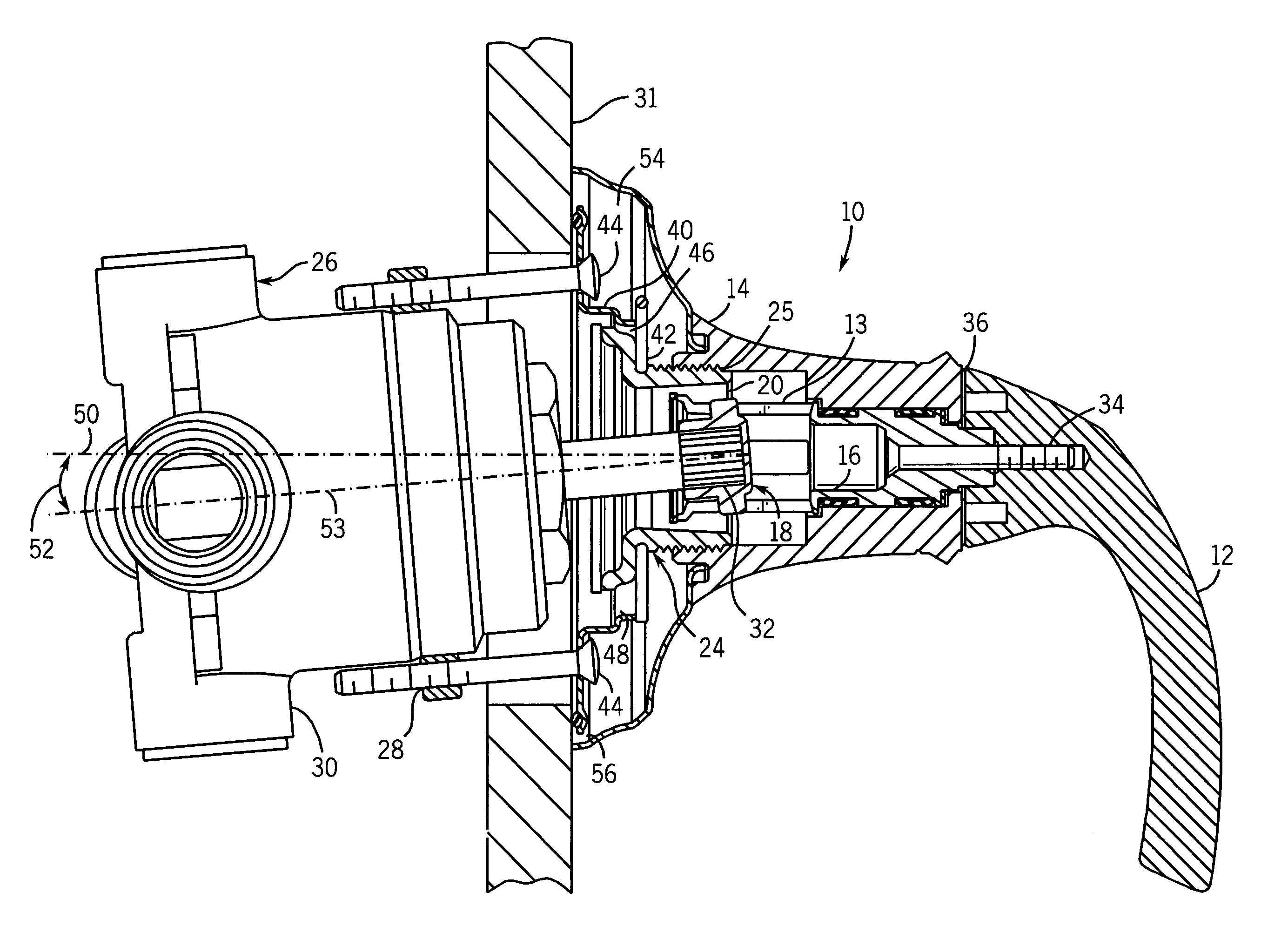
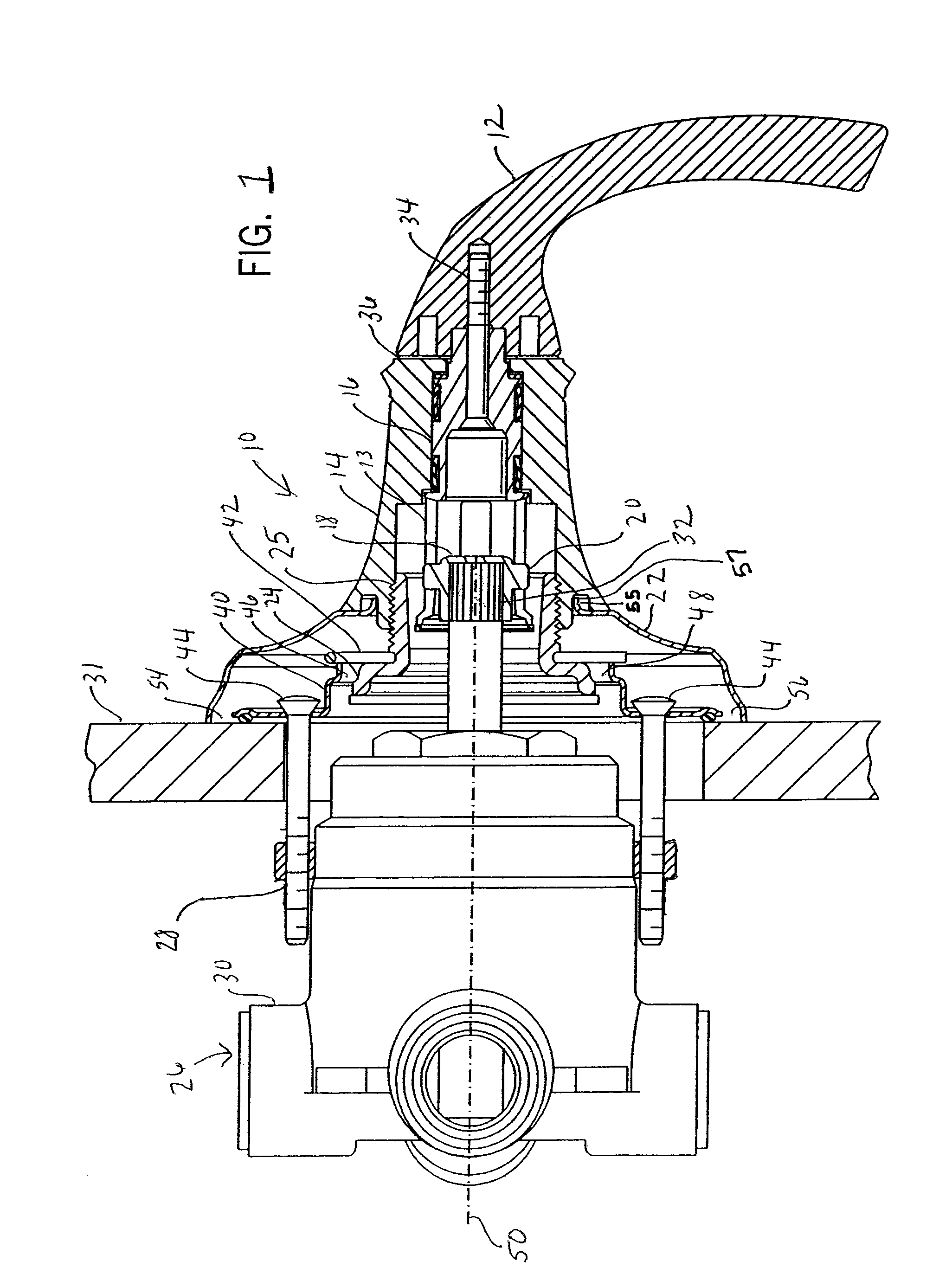
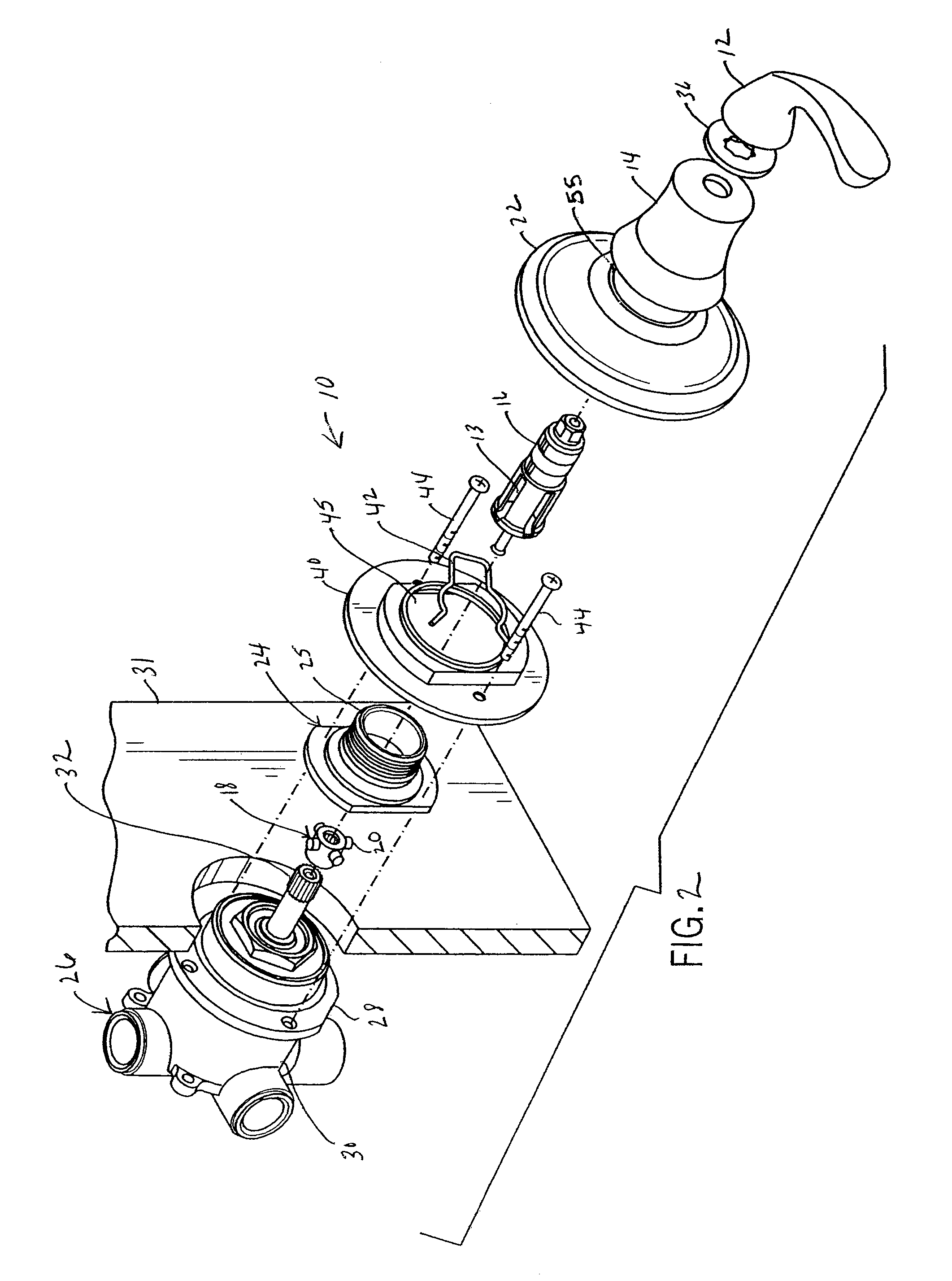
The invention provides a fluid valve assembly with a flexible coupling device that allows for misalignment between the valve stem and the handle, and can be easily positioned perpendicular to a wall or at an angle. The assembly includes a valve housing, a valve stem, a handle, and a flexible coupling device that connects the handle to the valve stem. The flexible coupling device can include slots and projections that allow for torque transfer, and can be positioned to center the valve stem within the mounting plate. The assembly can also include an escutcheon and a skirt for a better appearance when installed. The invention provides a quick and easy way to achieve a clean, professional look when installing fluid valves, and even in situations where the valve is not perfectly aligned.

Problems solved by technology

Problems can also result when the thickness of the wall is more or less than expected.
In any of these cases, the angle between the valve stem and the wall can be more or less than 90 degrees, which presents a number of functional and aesthetic problems for mounting the control hardware.
First of all, when the valve is not perpendicular to the wall, the handle and associated decorative elements can appear crooked and / or misaligned from inside the room.
Secondly, because of variations in the wall thickness the distance between the handle and the wall can vary, again affecting the aesthetics of the installation.
This gap may be unsightly, and in any event will leave an opening through which cold drafts can enter the bathroom and room moisture can leak from the room behind the room walls (possibly leading to mildew that is difficult to remove).
For some room materials (e.g. tile) this was difficult.
Further, this in any event required additional time and effort and occasionally led to a somewhat unprofessional appearance.
Additionally, while this correction eliminates the problem with the escutcheon, the problems with the handle remained.
Furthermore, the correction did not improve the appearance of the handle installation or account for differences induced by wall thickness.
While accounting for gaps between the wall and the escutcheon, however, this joint also does not correct for variations in the angle and distance of the handle to the wall.

Method used


Image

  • Valve assembly with compliant escutcheon
  • Valve assembly with compliant escutcheon
  • Valve assembly with compliant escutcheon

Examples


Embodiment Construction

[0037]Referring now to the figures and more particularly to FIGS. 1 and 2, a valve assembly (generally 10) of the present invention includes a handle 12, a skirt 14, a stem driver 16, a stem adapter 18, a seal plate 40, a clip 42, a decorative escutcheon 22, a mounting plate 24 and a main valve 26. One possible valve mechanism to be used inside the housing parts is that described in U.S. Pat. No. 5,467,799, the disclosure of which is hereby incorporated by reference as if fully set forth herein.

[0038]The valve 26 can include a housing or body 30 that includes apertures 28. The apertures 28 receive coupling devices such as threaded fasteners 44 to bolt a seal plate 40 provided on the room side of a wall 31 opposite the valve 24 to the valve 26.

[0039]Referring now also to FIG. 4, the seal plate 40 includes a raised flange 61 having a first and a second flat wall 60 and 62 on opposing sides of an aperture 45. The aperture 45 receives a mounting plate 24 which is retained against the wa...


PUM


Abstract

A fluid control valve includes flexible coupling between a handle and a valve stem which allows the components of the assembly on one side of a wall to be angularly misaligned with the components on the opposing side. Because the components adjacent to the room side of the wall can be mounted perpendicular to the wall, a decorative escutcheon can be mounted flush against the mounting wall when the wall or the valve is out of plumb.

Description

CROSS-REFERENCE TO RELATED APPLICATIONS[0001]Not applicable.STATEMENT OF FEDERALLY SPONSORED RESEARCH OR DEVELOPMENT[0002]Not applicable.BACKGROUND OF THE INVENTION[0003]The present invention relates to fluid control valves, and in particular to valve assemblies designed for use in mounting locations that are not perpendicular or square to a wall.[0004]Tub / shower fluid control valves are typically mounted through a wall adjacent a tub or a shower stall. The wall may be part of a unitary enclosure, or it may be a room wall such as a tiled wall forming part of a shower enclosure.[0005]Such control valves are typically anchored to rear studs and / or adjacent wall board, and then linked to hot and cold water supply lines behind the wall. These valves usually have a valve stem that projects outward from a wall opening, and a handle is attached to the outer end of the stem to provide control over the valve from the room side of the wall.[0006]Many of these valves are mixer valves which acc...

Claims


Application Information

Patent Timeline
Patent Type & Authority Patents(United States)
IPC IPC(8): F16L5/00F16K31/524
CPCF16D3/2057F16K31/605G05G1/12Y10T137/698Y10T137/6977F16K31/60F16D3/74F16K11/06
Inventor KAJUCH, PETE
Owner KOHLER CO
Learn More