Variable discharge sludge distributor

a distributor and variable technology, applied in the direction of valve housings, transportation and packaging, mechanical equipment, etc., can solve the problems large manure storage pits, and inability to achieve the effect of large manure production

Active Publication Date: 2009-03-31
HYDRO OPERATING
View PDF12 Cites 10 Cited by
  • Summary
  • Abstract
  • Description
  • Claims
  • Application Information

AI Technical Summary

Benefits of technology

[0016]In one embodiment, a sludge distributor includes a housing having a chamber within, an inlet, and a wall extending around the center axis, where the wall has a several orifices extending through the wall. The distributor may also include a rotatable portion rotatably disposed within the chamber about the axis, the rotational portion having a body and at least one sidewall connected to the body. The sidewall can be disposed only partially arcuately about the center axis, and be disposed to block at least some but not all of the orifices. Rotating the rotatable portion within the housing causes at least one sidewall to move past and block varying members of the orifices with varying rotational position.
[0018]Several pipe nipples may be secured to the housing about the orifices to provide a coupling point for a plurality of hoses coupled to the orifices. Some housing chambers have an interior wall disposed about the orifices, where the sidewall has an exterior surface that approaches within about ¼ inch or less from the wall interior surface. The sidewall may reduce flow through a blocked orifice by at least 50% relative to an unblocked orifice. Each sidewall may totally block a sight path between the center axis and an orifice when the sidewall is centered on the orifice, in some embodiments.
[0019]The present invention also can provide a sludge distributor having a central rotational axis therethrough and a longitudinal plane orthogonal to the axis, with the distributor including a housing having a cavity within, an inlet extending through the housing and into the cavity, and several orifices extending through the housing. The orifices can be disposed about the central axis and lie substantially within the plane. At least one baffle can be disposed within the housing cavity, be configured to travel rotationally about the central axis, and have an arcuate length disposed against and blocking at least one of the orifices. Rotating the at least one baffle within the housing about the central axis may block varying orifices with rotational travel of the baffle.

Problems solved by technology

Chickens, turkeys, pigs, and cows are often housed at a large facility, with the resulting generation of large quantities of manure.
The manure storage pit may be quite large in some instances.
While it is possible for a single farm to invest in the specialized equipment, and to use this equipment only twice a year, this is often not done.
If too much sludge is applied in an area, it may not be absorbed in to the ground, and may result in run-off.
Too much sludge in one spot may also be harmful to crop plants growing there.
Excessive sludge may also not be utilized by plants, with nitrates ending up in the ground water, an undesirable situation.
Too little sludge is also undesirable, as crops dependent on the sludge for fertilizer may receive little or no fertilizer.
Thus, an acceptable “average” sludge distribution consisting of alternating high and low areas along a crop row may result in unacceptable variations in crop growth.
If the backpressure built up within the distributor drops too low, then uneven sludge distribution will likely result.
If the backpressure becomes too high, then the sludge distribution may be even, but much energy is wasted.
It might be possible to meet this higher range, but at the cost of significantly higher pressure and the resultant energy wastage.
These large ranges are difficult to achieve without either wasting energy to maintain a large backpressure or dropping too low to insure even distribution.

Method used


Image

  • Variable discharge sludge distributor
  • Variable discharge sludge distributor
  • Variable discharge sludge distributor

Examples


Embodiment Construction

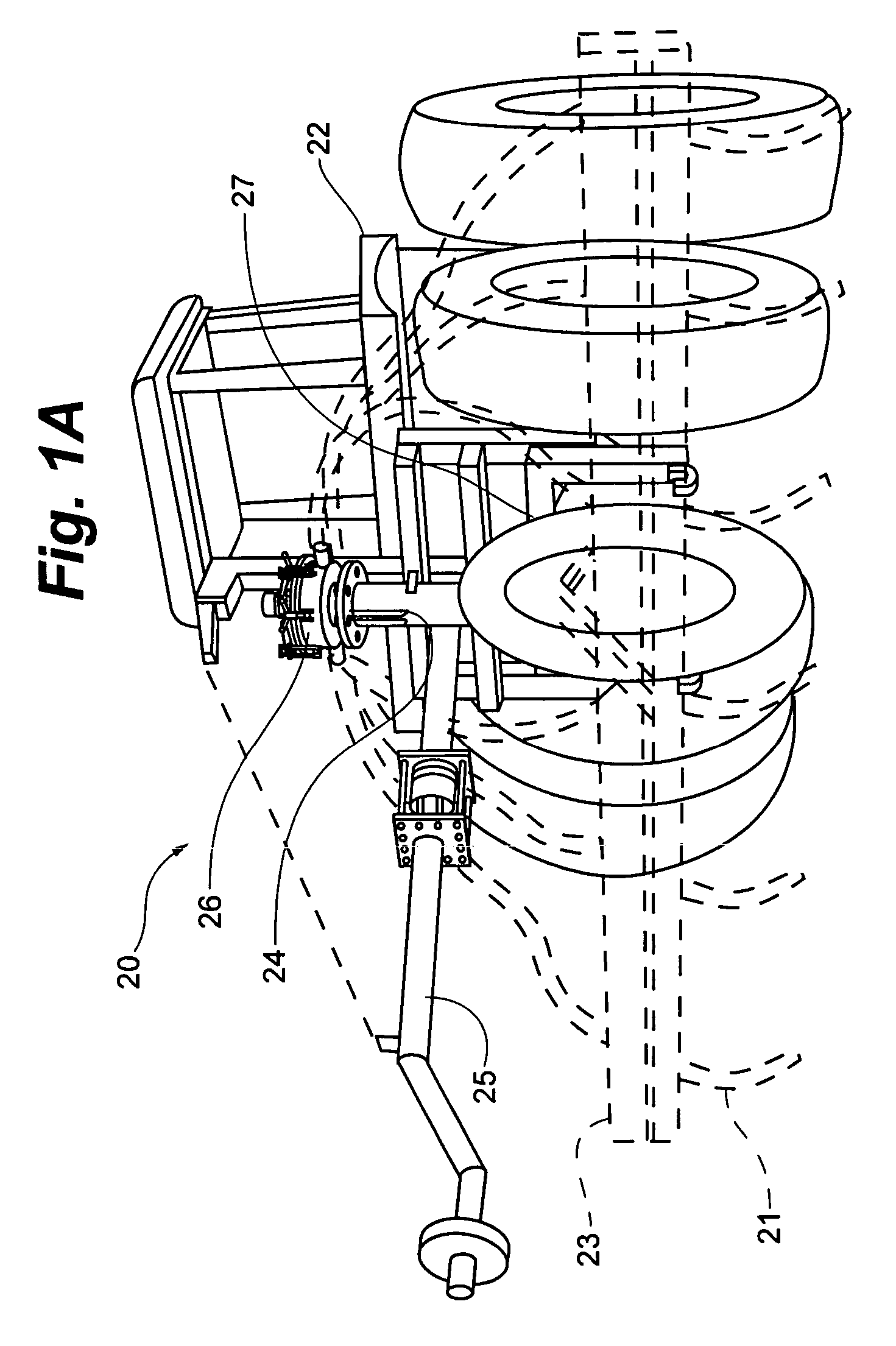
[0034]FIG. 1A illustrates a system 20 for distributing sludge on a field, including a tractor 22, a drag hose-three point hitch assembly 24, and a sludge distributor 26. As is discussed later, sludge distributor 26 generally includes a hydraulic motor atop the distributor and numerous outlets 36 disposed about the periphery for coupling to sludge distribution hoses 34. System 20 also includes a swing arm 25, a hitch 27, and an attached tool bar 23 carrying cultivator tillage equipment 21.

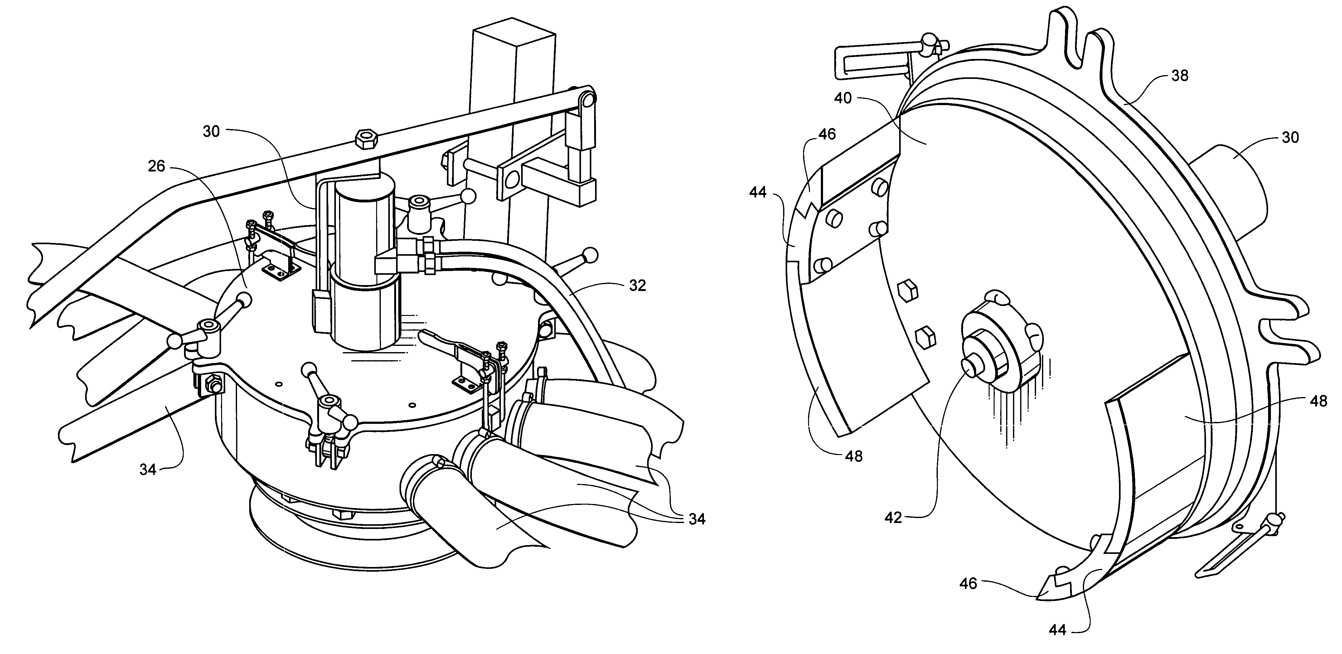
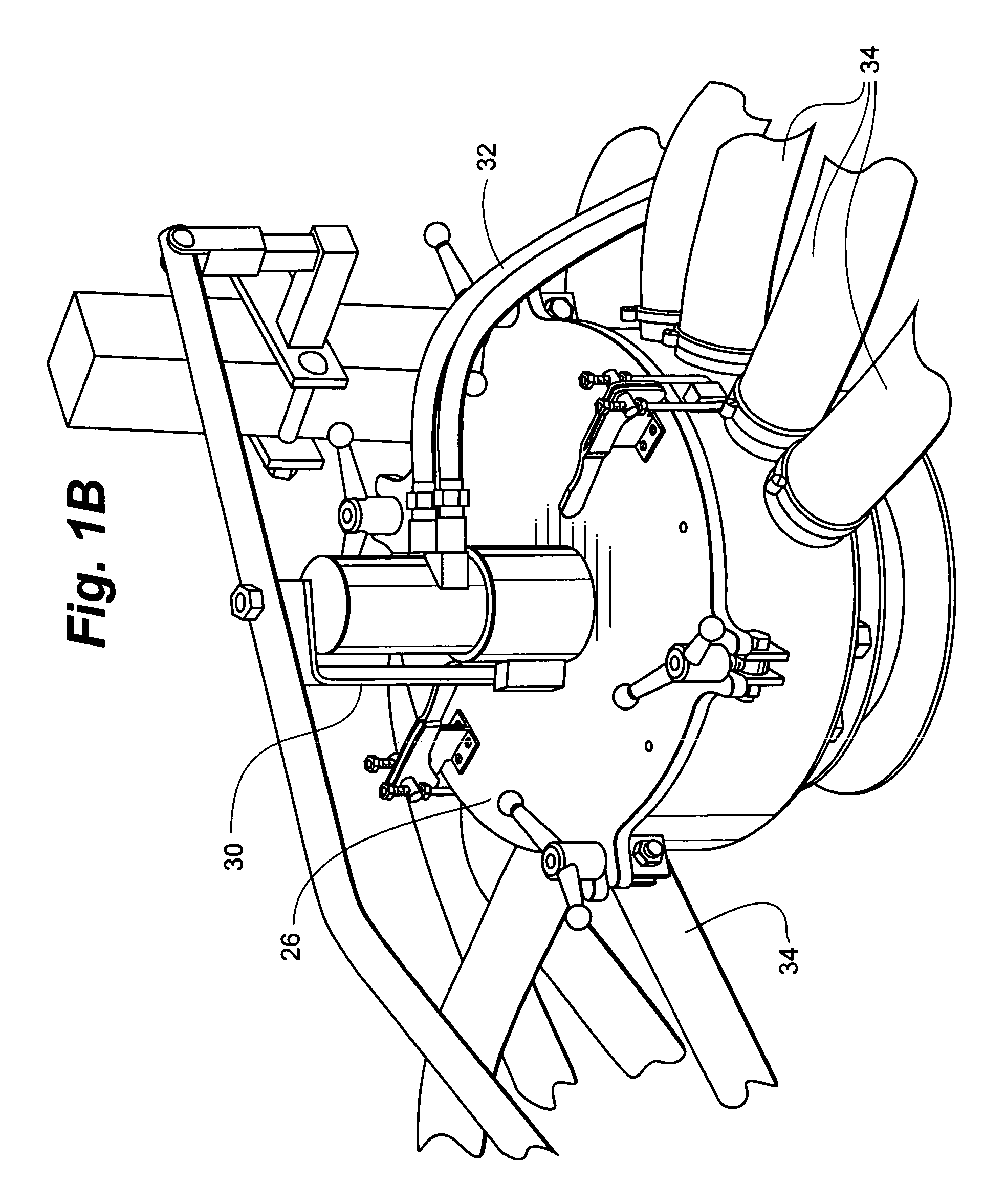
[0035]FIG. 1B illustrates the distributor of 26 of FIG. 1B, further illustrating a hydraulic motor 30 powered by hydraulic hoses 32. Sludge distributor 26 includes numerous sludge distribution hoses 34 coupled to the housing outlets 36 for distributing sludge to the field.

[0036]FIG. 2 illustrates sludge distributor 26 again showing hydraulic motor 30 coupled to a housing top plate or cover 38 which is clamped to the housing bottom portion, which includes several outlets 36 extending through the hous...


PUM


Abstract

Devices and methods for evenly distributing sludge, including manure and industrial sludge, to numerous hoses, over a large range of sludge supply pressures. Some devices include a housing having an inlet for receiving sludge under pressure and several outlets disposed outwardly through the housing cylindrical wall for coupling to hoses. The devices can include a rotating plate within the housing sweeping one or more baffles over the outlets to momentarily occlude the outlets and reduce flow through the occluded outlets. The baffles can include a first portion secured to the plate and a second portion removably secured to the first portion and / or the plate. Changing the total length of the baffles can change the affective cross-sectional area of the outlets available for flow at any instant in time. Increased sludge supply pressure may call for installing smaller sized baffles to reduce back pressure, while decreased sludge supply pressure may call for installing larger sized baffles to maintain sufficient back pressure to insure even flow. Even manure distribution onto fields over different pressure ranges can be provided.

Description

RELATED APPLICATIONS[0001]The present application is a non-provisional of U.S. Provisional Patent Application No. 60 / 605,941 filed Aug. 31, 2004, entitled VARIABLE DISCHARGE OCCLUSION SLUDGE DISTRIBUTOR, herein incorporated by reference in its entirety.FIELD OF THE INVENTION[0002]The present invention is related generally to devices for handling manure and sludge. More specifically, the present invention is related to sludge and manure manifolds for distributing pumped sludge to multiple hoses.BACKGROUND OF THE INVENTION[0003]Modern farming techniques often rely on efficiency of scale for survival and profitability. In one example, animal raising and feeding is often done at a central facility having a large number of animals. Chickens, turkeys, pigs, and cows are often housed at a large facility, with the resulting generation of large quantities of manure. This manure is collected and stored. The manure storage pit may be quite large in some instances. Some storage pits or lagoons ...

Claims


Application Information

Patent Timeline
Patent Type & Authority Patents(United States)
IPC IPC(8): A01C23/00F16K11/02
CPCA01C23/003F16K11/0853F16K27/0263Y10T137/86501Y10T137/86533Y10T137/5283A01C23/002
Inventor HUFFMAN, THOMAS R.
Owner HYDRO OPERATING
Why Eureka
Try Eureka