Code reader

a code reader and code technology, applied in the field of code readers, can solve the problems of difficult reading of dpm codes, and achieve the effect of great reliability

Active Publication Date: 2009-03-31
SICK AG
View PDF15 Cites 19 Cited by
  • Summary
  • Abstract
  • Description
  • Claims
  • Application Information

AI Technical Summary

Benefits of technology

[0007]It is an object of the invention to further develop a code reader of the initially named kind such that it is also suitable for the reading of DPM codes without the provision of a light source separate from the code reader, with the respective code in particular being able to be recognized with the greatest possible reliability.
[0010]In accordance with the invention, the provision of a separate light source is therefore avoided in an advantageous manner, which reduces the total economic effort of the arrangement and additionally also saves adjustment procedures between the light source and the code reader necessary in accordance with the prior art. In accordance with the invention, a compact device is made available which is to be accommodated in a single housing, is easy to handle and is suitable to read DPM codes without problem without the need for any additional components. This is achieved in that the light emergence surface of the light source integrated in the code reader is located much closer to the depth of field zone of the optical receiving system than to the optical receiving system itself.
[0013]In a preferred embodiment of the invention, the light source is located in the region of the optical receiving system and / or of the sensor matrix, with light directing elements being arranged between the light source and the light emergence surface. It is then possible in this case, for example, again to use conventional code readers in accordance with the prior art and also to use the light source integrated in code readers of this type. The light sources are namely as a rule arranged in the region of the optical receiving system and / or in the region of the sensor matrix in code readers in accordance with the prior art so that the named light directing elements can be positioned such that they direct the light radiated from the existing light source to the light emergence surface provided in accordance with the invention. The provision of an additional light source to the light source already present in a code reader in accordance with the prior art is accordingly no longer necessary. This embodiment can be realized particularly advantageously if the light directing elements and the light emergence surface are accommodated in an attachment detachable from the remaining code reader components. This attachment, which then only has reflecting surfaces and a light emergence surface designed, for example, as a light transmitting plate, can be manufactured in a cost-favorable manner and can be coupled in a simple manner to code readers in accordance with the prior art. A code reader in accordance with the invention can thus be realized with a very low economic effort.
[0016]In particular when light waveguides are used, but also when reflecting elements are used as light directing elements, it is preferred for lenses and / or diaphragms and / or ring reflectors for the generation of radiation directed in the direction of the light directing elements to be associated with the LEDs. In this process, a separate lens and / or a separate diaphragm and / or a separate ring reflector can in particular be associated with each LED. In this manner, the light radiation can be guided directly, efficiently and with little loss to the light emergence surface provided in accordance with the invention.

Problems solved by technology

The reading of DPM codes is difficult when the code reader is arranged perpendicular above the code, since the light source integrated in the code reader then illuminates the code at an angle of incidence which coincides at least largely with the optical axis of the code reader, which has the consequence that no great contrast difference occurs between the regions of the carrier material provided with recesses and those regions which do not have any recesses.
The fact is thus disadvantageous in the described known arrangements for the reading of DPM codes that the integrated light source usually present in a code reader cannot be used and an external light source additionally has to be provided which provides the described oblique illumination of the code.

Method used


Image

  • Code reader
  • Code reader
  • Code reader

Examples


Embodiment Construction

[0033]The following description of the preferred embodiments is merely exemplary in nature and is in no way intended to limit the invention, its application, or uses.

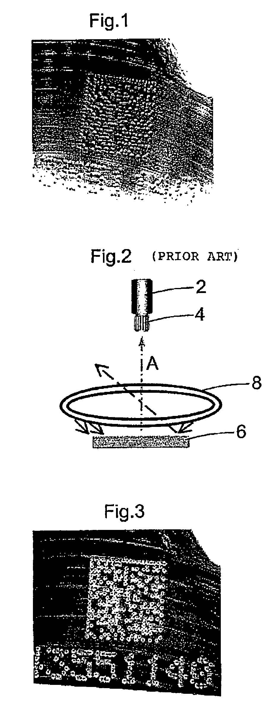
[0034]The code shown in FIG. 1 was introduced into a metal carrier by means of dot peening and consists of a square field of indentations arranged in a predetermined pattern, with each indentation having been produced by a needle impressed into the metal carrier. An arrangement of a plurality of numbers, likewise formed from individual indentations, are located beneath the square field.

[0035]The code in accordance with FIG. 1 cannot be recognized very easily since it was taken by a code reader with frontal illumination that is with a direction of illumination extending perpendicular to the carrier material.

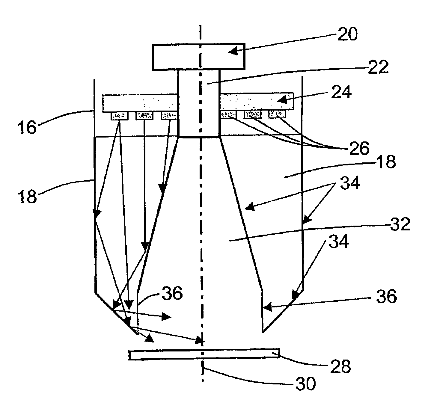
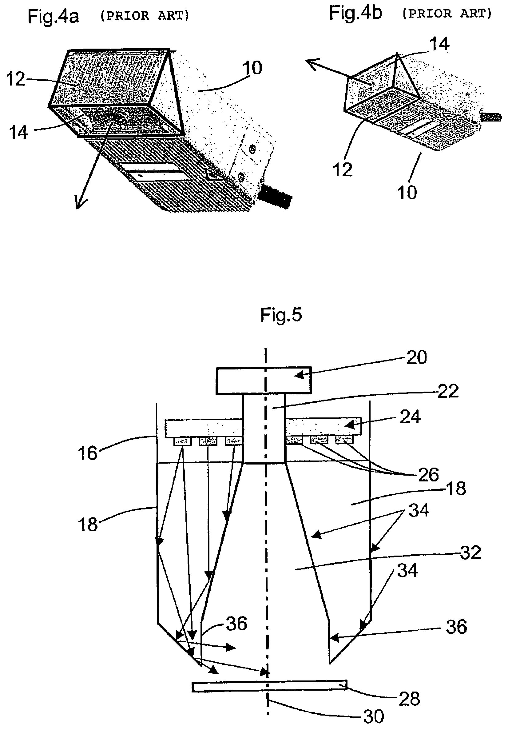
[0036]FIG. 2 shows a schematic representation of an arrangement in accordance with the prior art which is suitable for an improved reading of DPM codes, that is, for example, also of a code in accordance with FIG. 1. ...


PUM


Abstract

A code reader comprising an integrated light source for the illumination of a reading region, a sensor matrix and an optical receiving system positioned in front of the latter, wherein the light emergence surface of the light source is located in or closely in front of the depth of field zone of the optical receiving system.

Description

CROSS-REFERENCE TO RELATED APPLICATIONS[0001]This application claims the benefit of German Patent Application No. 10 2005 005 536.2, filed on Feb. 7, 2005. The disclosure of the above application is incorporated herein by reference.FIELD AND BACKGROUND OF THE INVENTION[0002]The invention relates to a code reader having an integrated light source for the illumination of a reading zone and having a sensor matrix and an optical receiving system positioned in front of said sensor matrix.[0003]Code readers are known in a variety of embodiments from the prior art and are also used inter alia to read codes which were applied directly to the respective carrier material by a deformation thereof. Codes of this type, which are known, for example, as so-called DPM codes (direct part marking codes), are generated, for example, in that the carrier material is acted on by a high-energy laser or by means of pin stamping (“dot peening”). It is common to both methods that recesses or indentations are...

Claims


Application Information

Patent Timeline
Patent Type & Authority Patents(United States)
IPC IPC(8): G06K7/10
CPCG06K7/10544G06K7/10732
Inventor REICHENBACH, JURGENRUNGE, WOLFRAMWEBER, HELMUT
Owner SICK AG
Why Eureka
Try Eureka