Substrate inspection method and apparatus
a substrate and inspection method technology, applied in the direction of semiconductor/solid-state device testing/measurement, image enhancement, instruments, etc., can solve the problems of small error in the positioning of substrates, inability to overcome errors, and inability to obtain incorrect inspection results, so as to improve inspection accuracy and reduce inspection area
- Summary
- Abstract
- Description
- Claims
- Application Information
AI Technical Summary
Benefits of technology
Problems solved by technology
Method used
Image

Examples
example 1
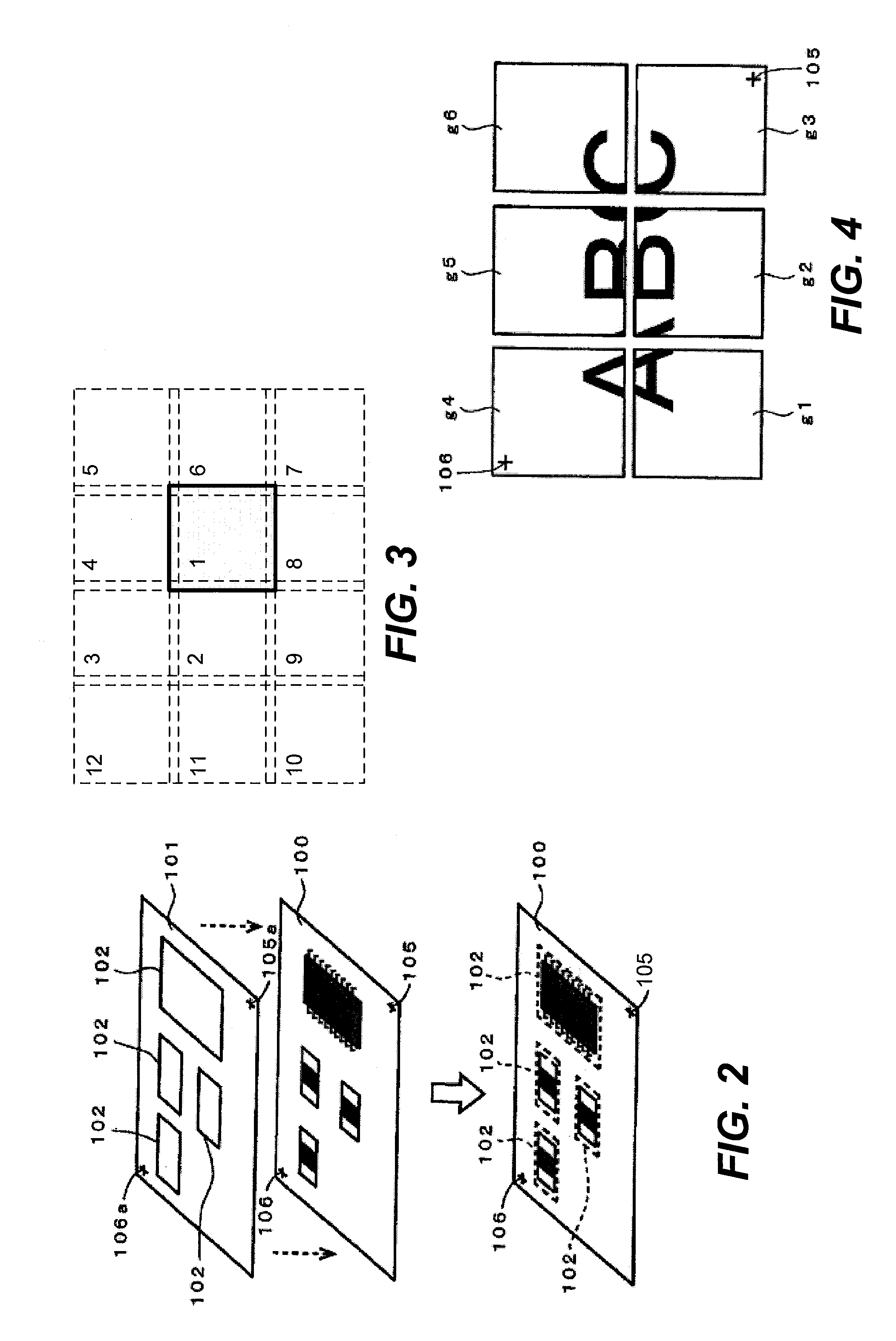
[0089]By this example, after the standard substrate 1S is divided into a plurality of areas to photograph, the images of the individual areas are connected together to produce a whole image of the standard substrate 1S and registered. Overlapped areas of width of a specified number of pixels are set between each pair of mutually adjacent areas corresponding to the error generated by the motions of the X-axis and Y-axis table control parts 6 and 7 (referred to as the machine error). On each of these images, a pattern matching process is carried out by using the image data of these overlapped portions and after the corresponding relationships of pixels are adjusted based on the result of this matching process, corresponding pixels are overlapped to obtain a correct whole image.
[0090]FIG. 3 shows an example of the process for overlapping images, the order in which the images are connected being indicated by circled numerals. In this example, one of the images in the center part is desi...
example 2
[0117]In this example and the examples that follow, methods of setting a target area and an inspection area and methods of detecting the displacement between a target image and a target area will be explained more in detail for the inspection of soldered portions (or fillets) of a component.
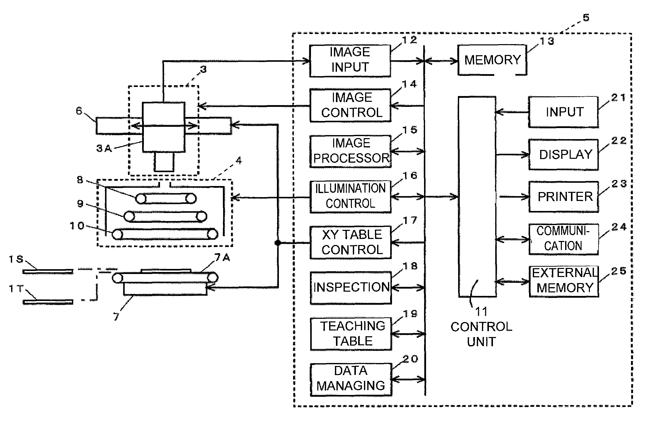
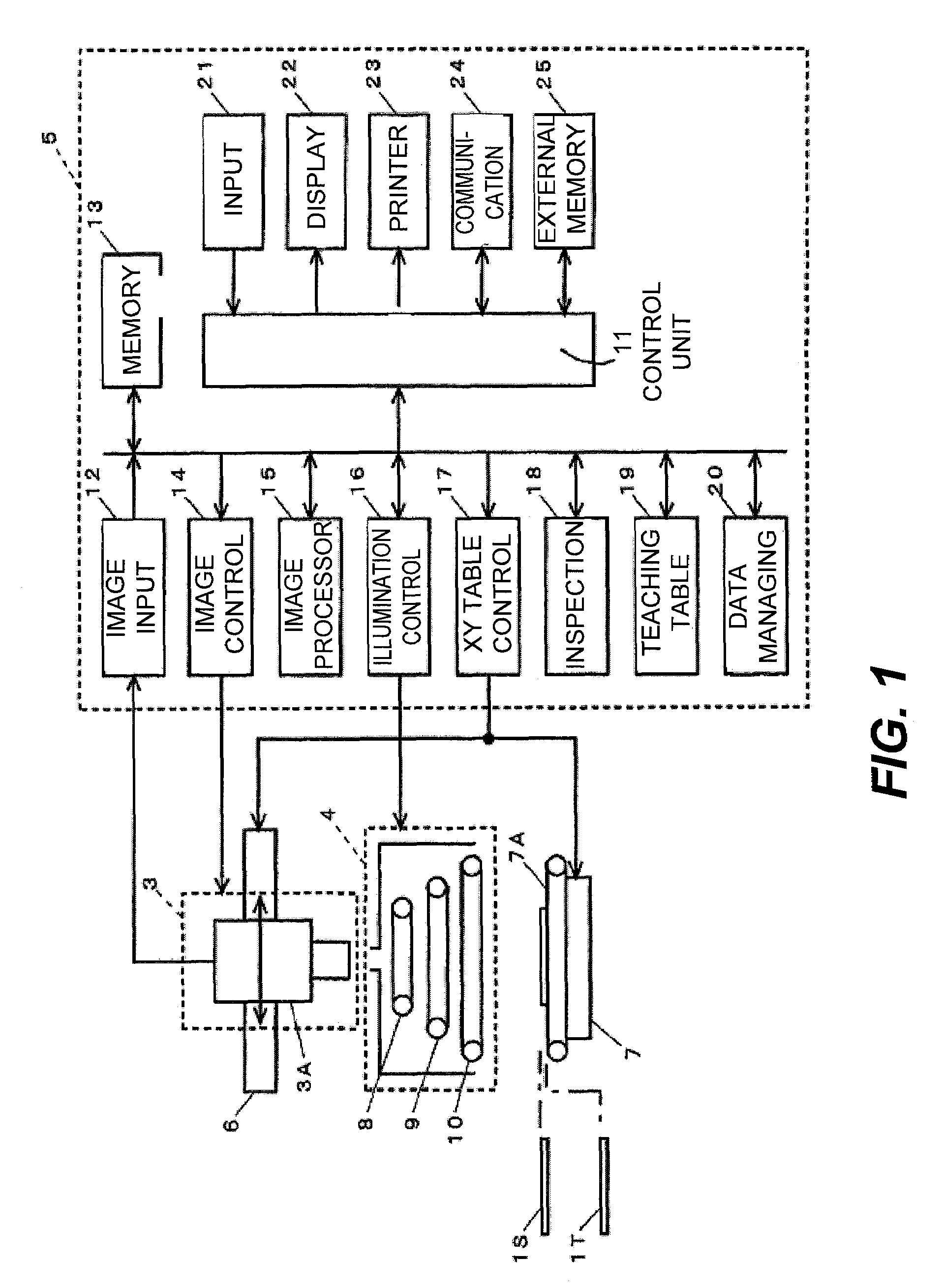
[0118]With a set-up as shown in FIG. 1, since the colored light from the light sources 8, 9 and 10 of the light emitting part 4 is normally reflected by the surface of a fillet, an image with red, green and blue colors distributed at a specified rate according to the slope of the fillet can be obtained. For the inspection of a fillet, these colors are independently extracted and their positions and areas are compared with standard values in order to judge the appropriateness of the sloped condition.
[0119]FIG. 10 shows the whole image 103 of a substrate. Like the example shown in FIGS. 4 and 5, this whole image 103 is also formed by superposing six images, that is, three images in the horizontal x...
example 3
[0137]Example 2 presumed that the target portion to be examined is contained within any one of the images that comprise the whole image. There are situations as shown in FIG. 15, however, where a component (QFP) 56 to be examined is positioned so as to span over a plurality of images. In such a situation, it is desirable to be able to set a target area at an arbitrarily selectable position on the whole image 103 as in the case of Example 1.
[0138]In Example 3, after the whole image 103 of the standard substrate 1S has been created, a target area 57 is set on this whole image 103 so as to wholly contain this component 56 in question and the setting position of this target area 57 is registered. The image inside the target area 57 is cut out and is registered as the standard image.
[0139]In the above, the setting of the target area 57 can be carried out by using the map image of the substrate but another method is to display the whole image 103 on the display part 22 and to receive the ...
PUM
 Abstract
Description
Claims
Application Information
 - R&D
- Intellectual Property
- Life Sciences
- Materials
- Tech Scout
- Unparalleled Data Quality
- Higher Quality Content
- 60% Fewer Hallucinations
Browse by: Latest US Patents, China's latest patents, Technical Efficacy Thesaurus, Application Domain, Technology Topic, Popular Technical Reports.
© 2025 PatSnap. All rights reserved.Legal|Privacy policy|Modern Slavery Act Transparency Statement|Sitemap|About US| Contact US: help@patsnap.com