
Roadside equipment clock accuracy test method and system based on floating vehicle

A technology of roadside equipment and inspection method, which is applied to the traffic control system of road vehicles, service based on location information, service based on specific environment, etc. The effect of accuracy and stability

Active Publication Date: 2020-12-29
NANJING MICROVIDEO TECH
View PDF5 Cites 4 Cited by
  • Summary
  • Abstract
  • Description
  • Claims
  • Application Information

AI Technical Summary

Problems solved by technology

However, this method can only provide limited assistance in troubleshooting clock errors caused by the above-mentioned factors. For clock anomalies caused by factors such as timing network delays or internal calculation errors, a third party uses accurate clocks and device clocks at each device Time is more ideal
However, from the perspective of cost and feasibility, it is not realistic to arrange special regular reciprocating inspections for personnel

Method used


Image

  • Roadside equipment clock accuracy test method and system based on floating vehicle
  • Roadside equipment clock accuracy test method and system based on floating vehicle
  • Roadside equipment clock accuracy test method and system based on floating vehicle

Examples


Embodiment 1

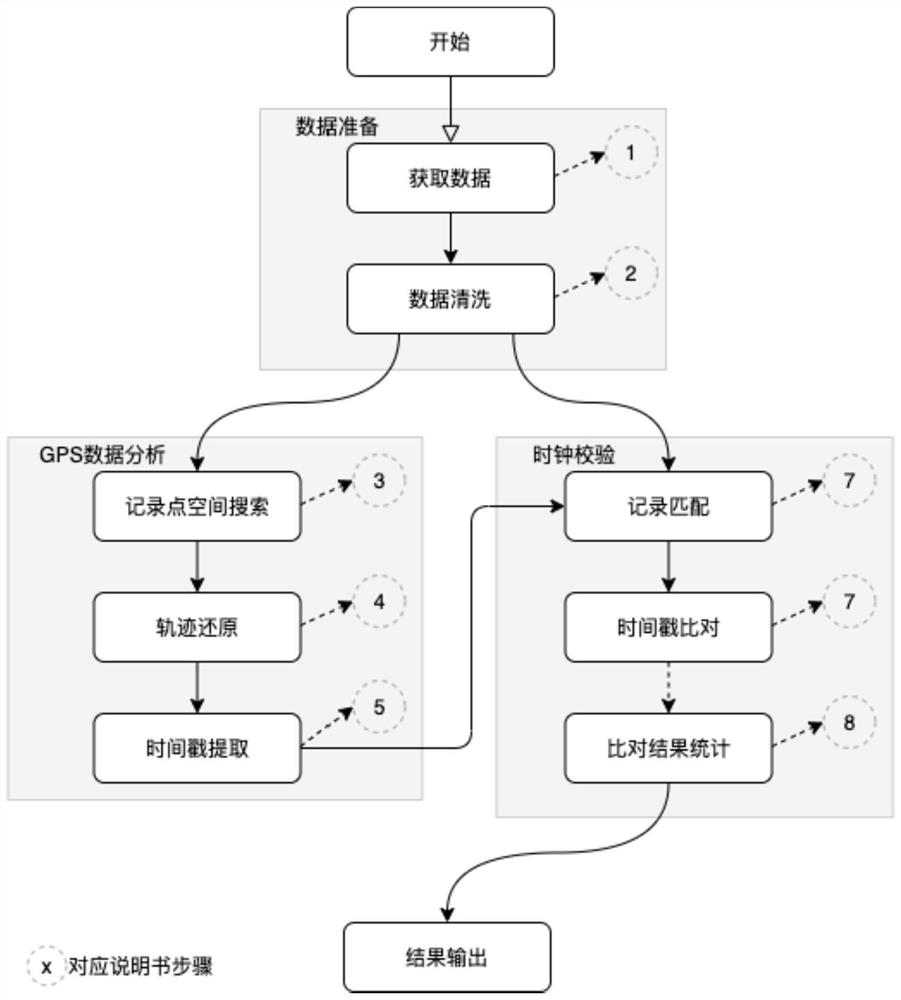
[0046] The method process of the present invention is as figure 1 shown, including:

[0047] 1. Prepare the input data for realizing the technical solution.

[0048] This program needs to use input data from three sources: 1) basic data, 2) spatio-temporal data collected by the GPS equipment of the floating vehicle (data set V), and 3) observation data of vehicles by roadside equipment (data set G).

[0049] Basic data includes basic information of roadside equipment and vehicles, such as:

[0050] Roadside equipment number, the unique number used to identify roadside equipment;

[0051] Roadside equipment spatial location information, at least including longitude and latitude information;

[0052] Vehicle basic information, such as: vehicle identification information (such as license plate), model, color, etc.

[0053] Floating car data (represented as data set V) describes the vehicle spatial position records collected by the vehicle GPS device at a fixed frequency withi...

Embodiment 2

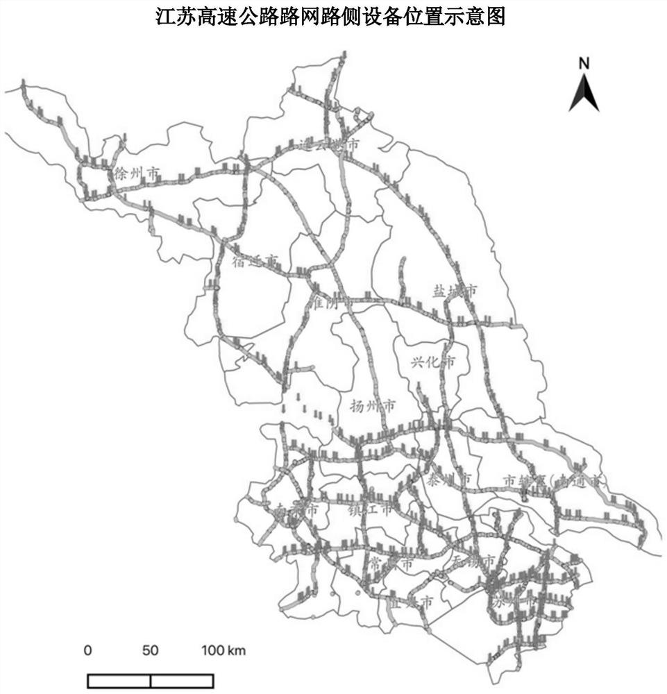
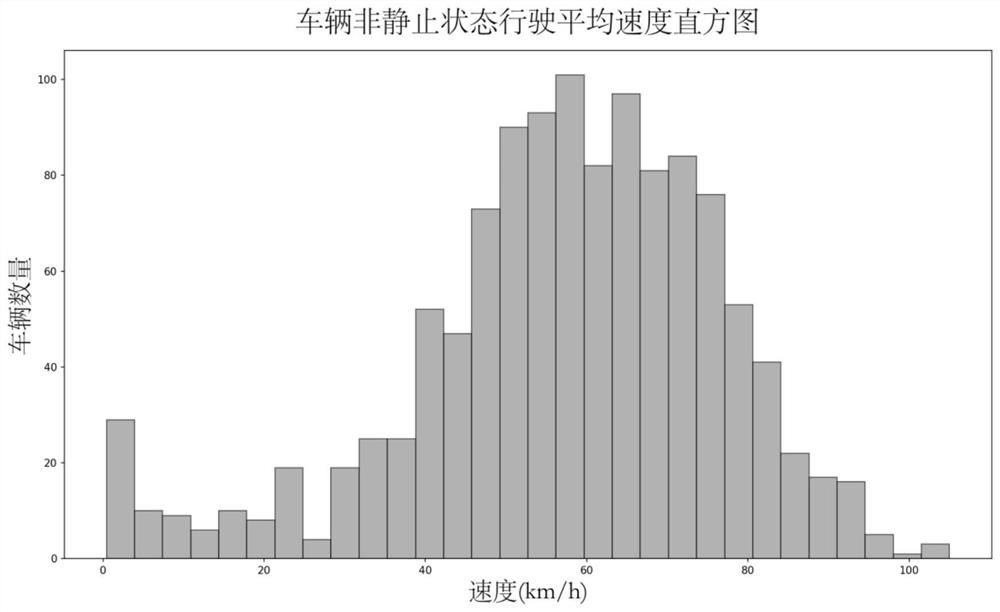
[0132] This case is carried out based on the highway network in Jiangsu and its roadside equipment. The total mileage of the case study area is about 4084 kilometers, including 1316 roadside equipment. Floating vehicles are expressway obstacle removal vehicles, sweeping vehicles, and patrol police vehicles. All vehicles are equipped with GPS positioning systems, and their position and movement information are reported to the system in real time.

[0133] The implementation of this case is based on the development and implementation of a private cloud environment. The host hardware environment is: 1) Intel(R) Xeon(R) Gold5218R x 2CPU; 2) 256GB memory; 3) 1Tb SSD+16Tb HDD. The virtual host used for data processing and analysis is configured with 40 cores and 128Gb memory. The system platform is Ubuntu 18.04LTS. The analysis software platform is JupyterLab. The analysis uses python 3.7. Third-party tools include: numpy, pandas, sklearn, matplotlib, etc.

[0134] The implementatio...


PUM


Abstract

The invention relates to a roadside equipment clock accuracy test method and system based on a floating vehicle, and the method comprises the steps: retrieving and recording GPS records nearby roadside equipment, including vehicle GPS positioning information and time information; forming a passing track record of the vehicle passing by the roadside equipment based on the obtained GPS record; basedon the GPS positioning information of the vehicle passing through the roadside equipment each time, establishing a fitting model to predict the real GPS time of the vehicle passing through the roadside equipment; and matching data records of the same vehicle passing through the same road side equipment, and checking whether the observation time of the road side equipment is consistent or not by utilizing the real GPS time when an event occurs. The method and the system are low in cost and easy to implement, and have good accuracy and stability.

Description

technical field [0001] The invention belongs to the field of highway operation and management informatization, and relates to a method and an application system for realizing clock calibration of roadside equipment by using floating car data. Background technique [0002] The extensive construction of highway roadside equipment (Road Side Unit, RSU) has greatly enhanced the field perception ability of highway operation management. As an end-sensing infrastructure, the built-in clock of the RSU device provides time information when it is working. In actual engineering, the clock error of the RSU device often occurs, causing the data provided by the device to carry the wrong time stamp. There are many reasons for this phenomenon, for example: 1) The internal clock of the device has not been corrected (time service) or is set incorrectly; 2) The built-in clock of the device has been running for a long time to produce errors; 3) The device is caused by external factors such as ...

Claims


Application Information

Patent Timeline
Patent Type & Authority Applications(China)
IPC IPC(8): H04W4/029H04W4/40H04W56/00G08G1/01
CPCH04W4/029H04W4/40H04W56/003G08G1/0116
Inventor 朱磊齐家卞加佳
Owner NANJING MICROVIDEO TECH
Learn More