
Shock absorber assembly

a technology of shock absorber and assembly, which is applied in the direction of vibration dampers, springs, program control using stored programs, etc., can solve the problems of double-action valve devices and relatively complex, and achieve the effect of reducing the temperature of the assembly

Active Publication Date: 2009-04-07
ROBERTSON GRAEME KERSHAW
View PDF32 Cites 76 Cited by
  • Summary
  • Abstract
  • Description
  • Claims
  • Application Information

AI Technical Summary

Benefits of technology

The solution simplifies the construction of the valve body, reduces heat buildup, and enhances damping control, allowing for adjustable damping characteristics and reduced incidence of 'bottoming out' in suspension systems, particularly in heavy-duty applications.

Problems solved by technology

The valve devices are typically double-acting and so are relatively complex, requiring separate ducting and separate one-way valving for each direction of flow.

Method used


Image

  • Shock absorber assembly
  • Shock absorber assembly
  • Shock absorber assembly

Examples


Embodiment Construction

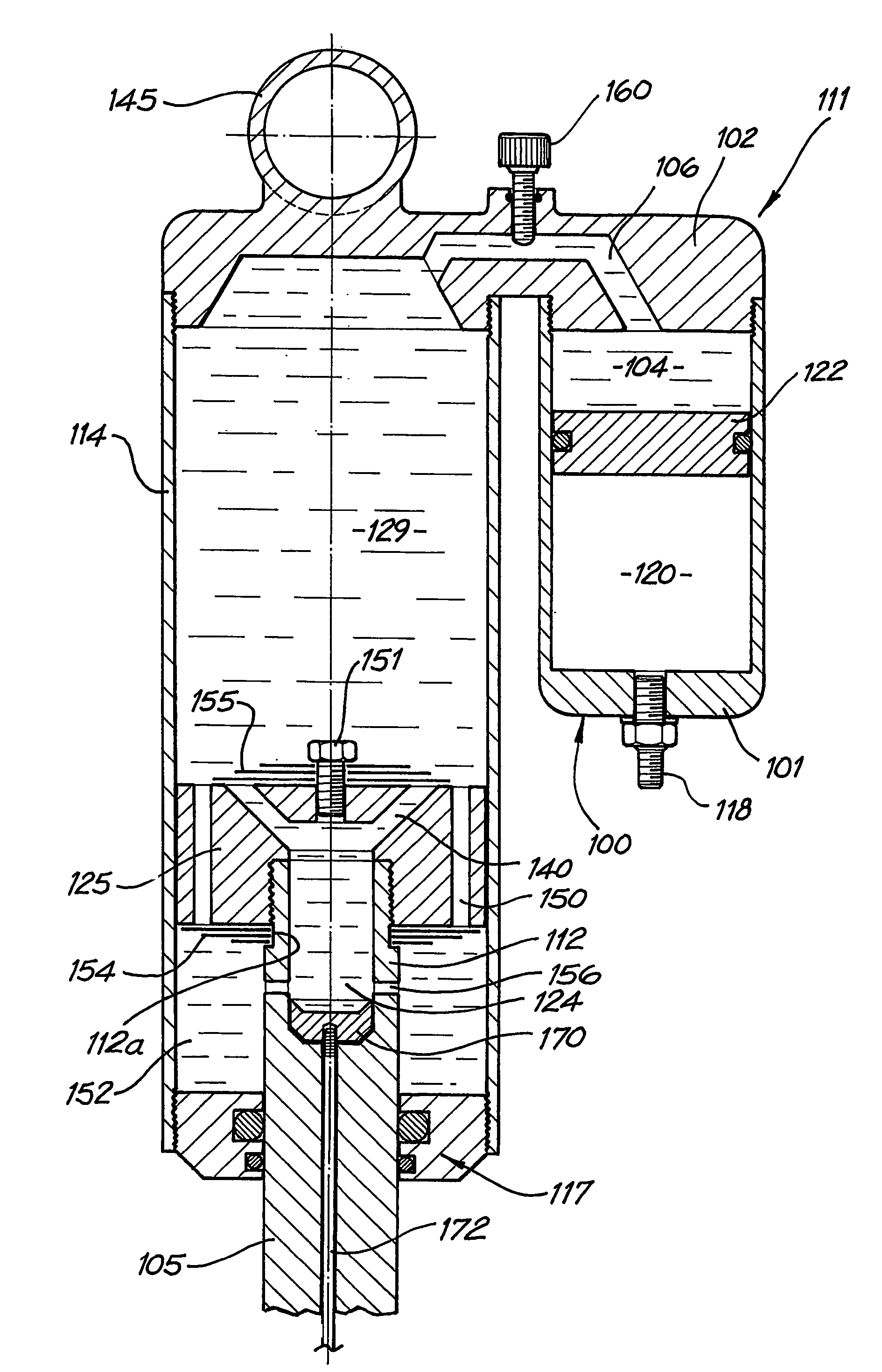
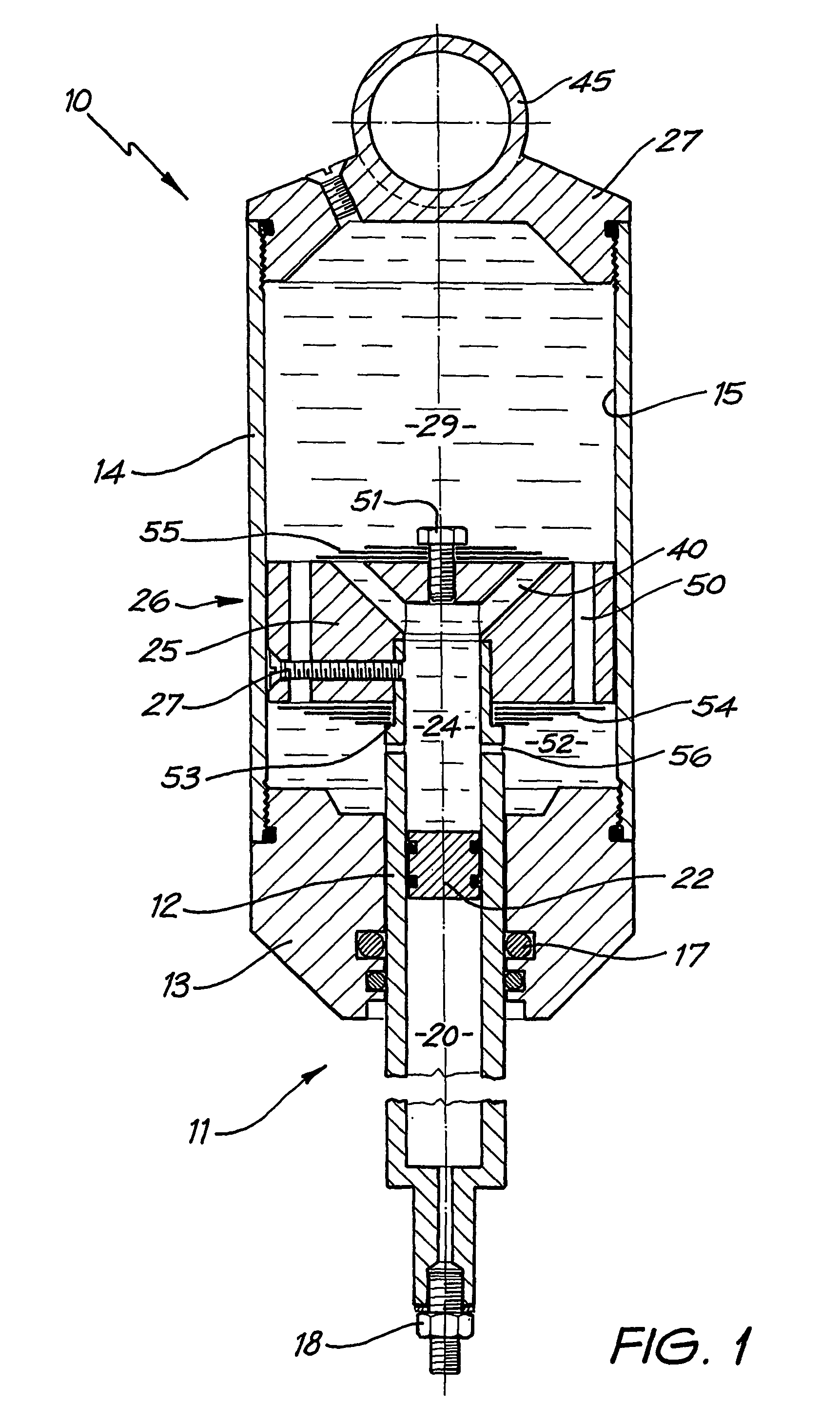
[0017]The shock absorber assembly illustrated in FIG. 1 is an integrated shock absorber unit 10 that includes pressurised-gas cushioning means 11 and would typically be one of a number of such units forming auxiliary components of a suspension system in a vehicle. The units may be acting individually or be linked in a fluid circuit to provide a managed and balanced suspension response.

[0018]Shock absorber unit 10 has a first cylindrical tube 12 received within a second cylindrical tube 14 so that the two tubes constitute mutually reciprocably moveable parts. Tube 12 is connected to tube 14 through a head 13 of tube 14 that includes a sealing configuration 17 about tube 12.

[0019]Tube 12 incorporates gas cushioning means 11 and to this end is provided, in this case at its outboard or proximal end, with a filling valve 18 for introducing gas, such as nitrogen or similar, under pressure into the tube 12 to fill a first cavity or chamber 20 located at or towards the proximal end of tube ...


PUM


Abstract

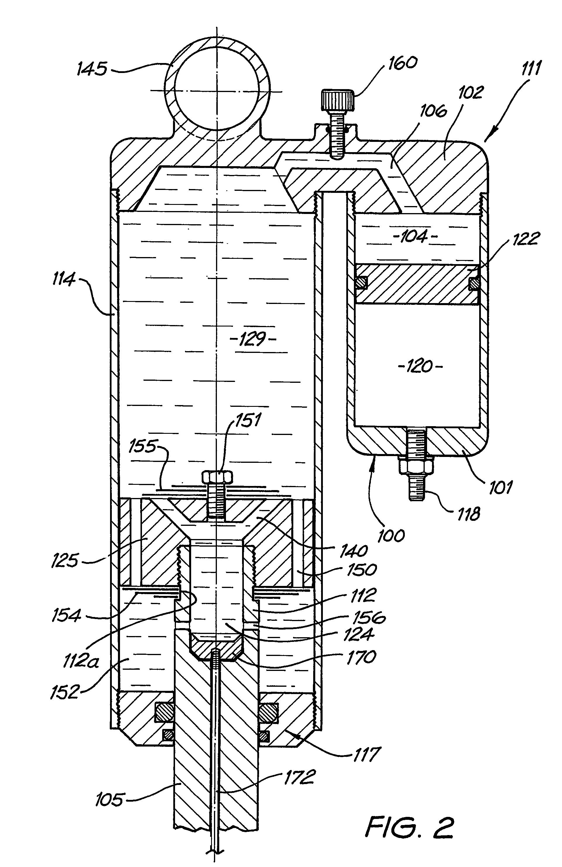
A shock absorber assembly includes a motion damping means that is filled with a fluid in operation and has a pair of relatively moveable parts (12, 14) and valve means (26) permitting flow of the fluid between the parts. The parts comprise a first part (12) and a second part (14) in which the first part is receivable whereby the parts are arranged for relative retracting and extending movement during which fluid is forced through the valve means (26) at respective predetermined controlled flow rates so as to dampen the movement. The relatively moveable parts contain respective primary chambers (24, 29) for the fluid. The first part is substantially smaller in cross-section than the second part to define an intermediate chamber (52) about the first part within the second part. Lateral port means (56) communicates the intermediate chamber (52) and the primary chamber (24) of first part (12). The flows at respective predetermined controlled flow rates are limited to respective flows (i) directly from the primary chamber (24) of the first part (12) to the primary chamber (29) of the second part (14) and (ii) via the intermediate chamber (52) and lateral port means (56) from the primary chamber (29) of the second part (14) to the primary chamber (24) of the first part (12).

Description

FIELD OF THE INVENTION[0001]This invention relates generally to shock absorbers but is particularly useful for shock absorber assemblies in vehicle suspension systems, especially in heavy duty applications such as trucks and industrial vehicles, and off-road racing vehicles. The invention will primarily be described in this context in this specification but it will be understood that the invention is broadly applicable to shock absorbers in general. Other applications include motorcycles, industrial machinery, industrial switch gear systems, and suspension systems for seats, particularly vehicle seats, truck cab suspensions or the like.BACKGROUND ART[0002]Vehicle suspension systems fall into a variety of broad sub-classes according to the mechanism by which motion is damped and smoothed. One such sub-class relies on a fluid system in which a suitable, typically substantially incompressible, fluid is forced through one or more valve devices at one or more predetermined controlled rat...

Claims


Application Information

Patent Timeline
Patent Type & Authority Patents(United States)
IPC IPC(8): F16F9/14F16F9/06G06F9/06
CPCF16F9/063F16F9/32
Inventor ROBERTSON, GRAEME KERSHAW
Owner ROBERTSON GRAEME KERSHAW
Learn More