Weather radar system and method using data from a lightning sensor

a technology of weather radar and lightning sensor, which is applied in direction finders using radio waves, instruments, and reradiation, etc., can solve the problems of lightning, high winds, lightning, hail, and other weather hazards, and lightning sensors do not have the ability to accurately and precisely locate and identify convective weather cells

Active Publication Date: 2009-04-07
ROCKWELL COLLINS INC
View PDF43 Cites 92 Cited by
  • Summary
  • Abstract
  • Description
  • Claims
  • Application Information

AI Technical Summary

Problems solved by technology

Convective weather cells can produce turbulence, high winds, lightning, hail, and other weather hazards.
However, lightning sensors do not have the ability to accurately and precisely locate and identify convective weather cells.
Heretofore, lightning detection systems have not been effectively utilized with aircraft weather radar systems.
Generally, lightning sensors have the ability to detect lightning strikes at long range, but cannot locate the distance to such lightning striking with a high degree of accuracy.
High performance weather radar systems can detect weather at substantial ranges but at some ranges have difficulty in determining whether or not an illuminated weather cell is hazardous.
Weather radar systems that utilize spectral width methods to ascertain weather hazards are generally used at ranges less then forty nautical miles because these methods are not as accurate at ranges greater then forty nautical miles.
However, weather radar systems utilizing hazard detection methods based upon vertical reflectivity are limited in accuracy at longer ranges because the smaller antenna diameter of these systems prevents more accurate estimations of storm height.
When the weather radar system indicates hazardous weather in response to this weather phenomena, the weather radar system unnecessarily provides hazard warnings and behaves more like a simple rain gauge than a hazard detector.
However, lightning sensors and lightning detection systems are generally not provided on aircraft because of their inherent range inaccuracy even though they provide accurate bearing estimations.
Further, lightning detection by lightning sensors is generally only spatially correlated with hail and turbulence at scale lengths comparable to or greater than a typical size of a convective weather cell.
Therefore, a lightning sensor is most accurate at pointing to the bearing of a cell that is producing lightning, and is less accurate at producing a range estimate to a hazard and identifying an aircraft sized path of safe passage.

Method used


Image

  • Weather radar system and method using data from a lightning sensor
  • Weather radar system and method using data from a lightning sensor
  • Weather radar system and method using data from a lightning sensor

Examples


Embodiment Construction

[0030]Before describing in detail the particular improved system and method, it should be observed that the invention includes, but is not limited to a novel structural combination of conventional data / signal processing components and communications circuits, and not in the particular detailed configurations thereof. Accordingly, the structure, methods, functions, control and arrangement of conventional components software, and circuits have, for the most part, been illustrated in the drawings by readily understandable block representations and schematic diagrams, in order not to obscure the disclosure with structural details which will be readily apparent to those skilled in the art, having the benefit of the description herein. Further, the invention is not limited to the particular embodiments depicted in the exemplary diagrams, but should be construed in accordance with the language in the claims.

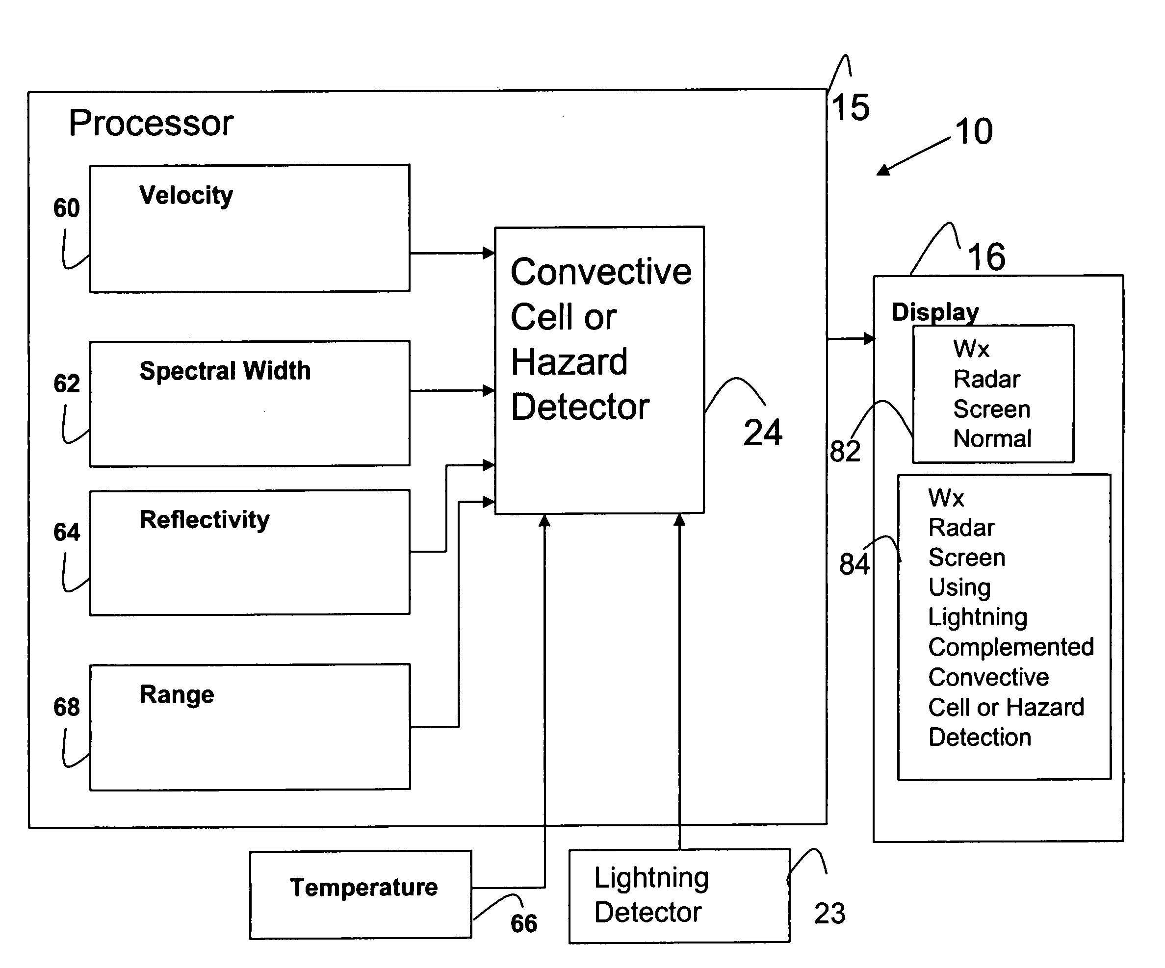
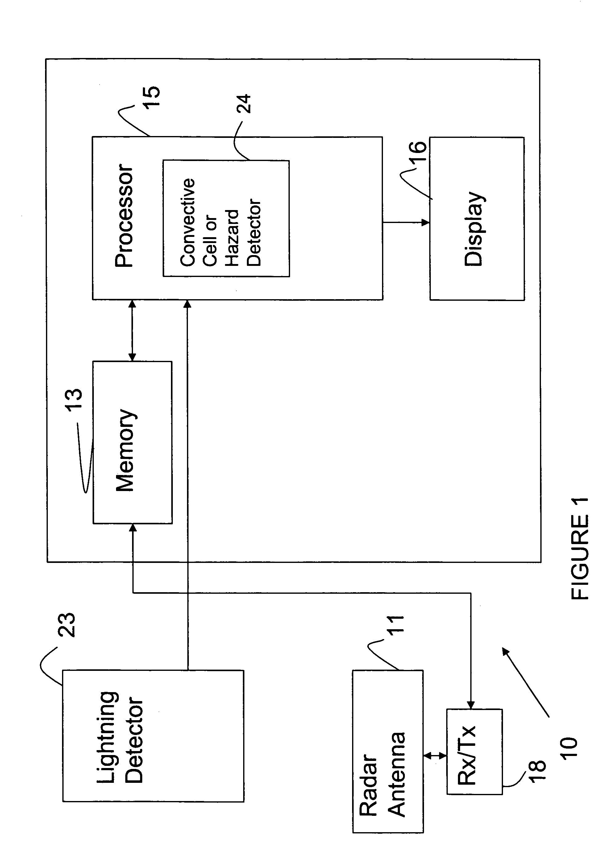
[0031]Referring now to FIG. 1, a weather radar system 10 which may be used on an ai...


PUM


Abstract

A weather radar system or method can be utilized to determine a location of a weather hazard for an aircraft. The weather radar system can utilize processing electronics coupled to an antenna. The processing electronics can determine presence of the hazard in response to data related to returns received by the weather radar antenna and data from a lightning sensor. The system can include a display for showing the hazard and its location.

Description

FIELD OF THE INVENTION[0001]The present application relates generally to the identification of hazards or potential hazards. More particularly, the present application relates to a method of and a system for identifying convective and non-convective cells using a weather radar system.BACKGROUND OF THE INVENTION[0002]U.S. Pat. No. 6,424,288 invented by Daniel L. Woodell and assigned to the assignee of the present application discloses a system for and methods of displaying radar information using weather radar systems. U.S. patent application Ser. No. 11 / 153,972, filed on Jun. 16, 2005, now U.S. Pat. No. 7,307,583 by Daniel L. Woodell and assigned to the assignee of the present application discloses a weather radar system for detecting hazardous and potentially hazardous weather. U.S. Pat. No. 6,201,494 filed on Jul. 30, 1999 by Kronfeld and assigned to the assignee of the present application discloses an automatic storm finding weather radar. U.S. Pat. No. 6,577,947, filed on Mar. 1...

Claims


Application Information

Patent Timeline
Patent Type & Authority Patents(United States)
IPC IPC(8): G01S13/95G01S13/86G01W1/00G01S13/00
CPCG01S7/22G01S13/86G01S13/953G01W1/02G01S2007/403Y02A90/10G01S7/403
Inventor WOODELL, DANIEL L.KRONFELD, KEVIN M.
Owner ROCKWELL COLLINS INC
Why Eureka
Try Eureka