Fan field replaceable unit

a technology of replacing units and fan bodies, applied in the field of rack mount enclosures, can solve problems such as and achieve the effect of avoiding the failure of the installed fan assembly

Inactive Publication Date: 2009-04-07
CISCO TECH INC
View PDF22 Cites 61 Cited by
  • Summary
  • Abstract
  • Description
  • Claims
  • Application Information

AI Technical Summary

Problems solved by technology

Suppose that an installed fan assembly suf

Method used


Image

  • Fan field replaceable unit
  • Fan field replaceable unit
  • Fan field replaceable unit

Examples


example embodiments

Description of Example Embodiments

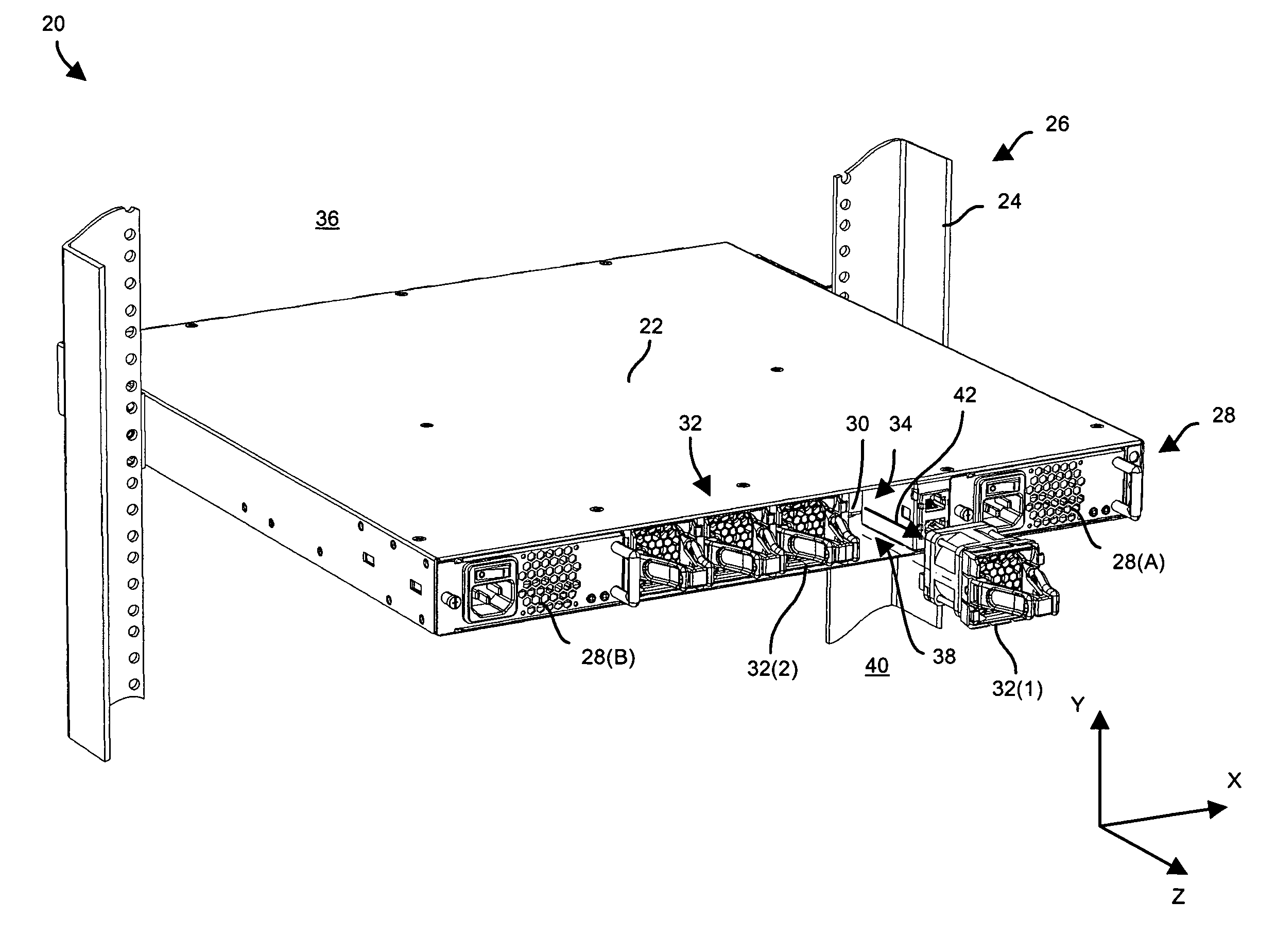
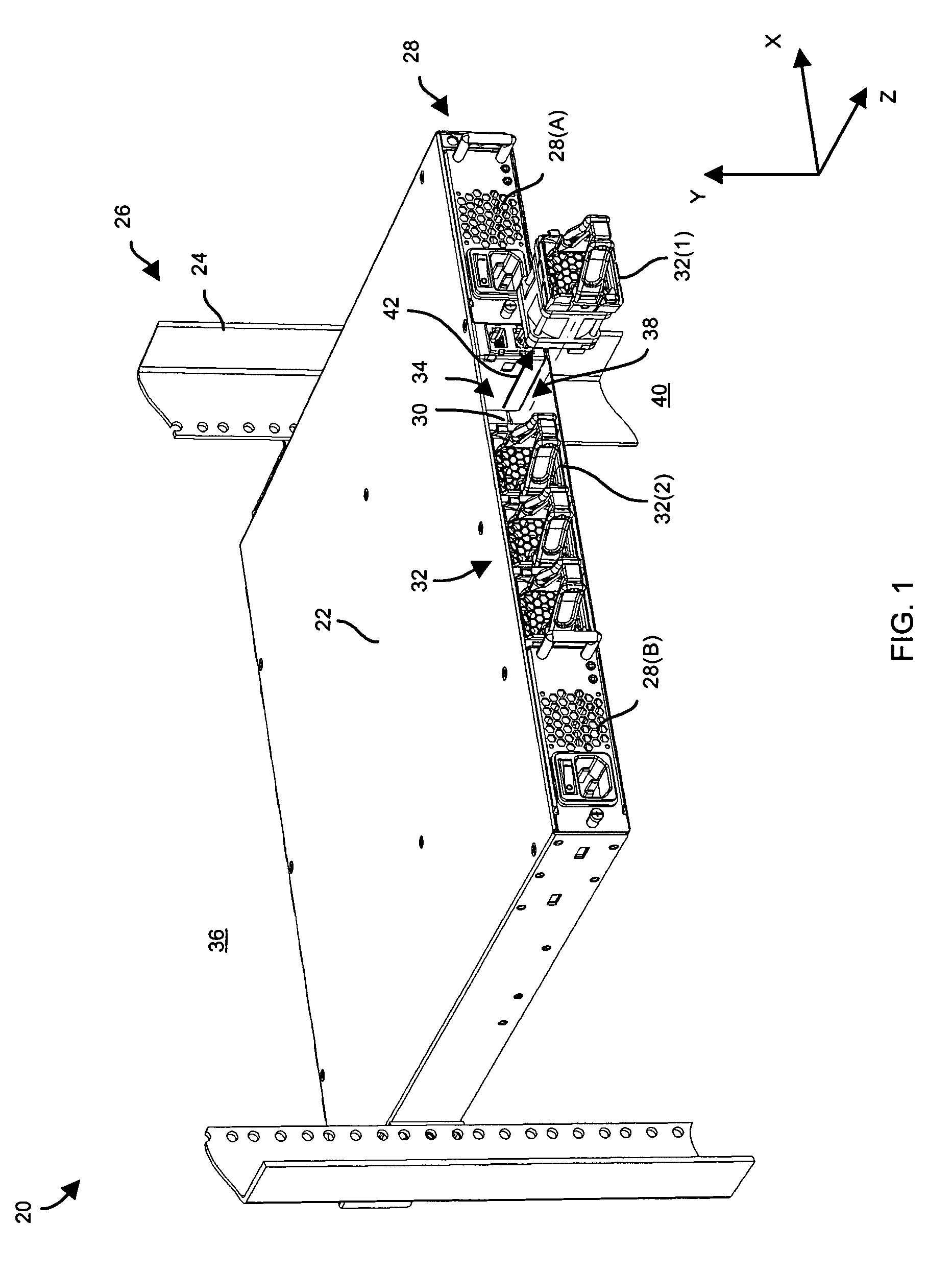
[0018]FIG. 1 shows an electronic system 20 having multiple field replaceable fan devices. It should be understood that the electronic system 20 is described below in the context of rack mount equipment by way of example only and that the electronic system 20 is capable of being implemented in other ways, e.g., in stand alone configurations, in custom frames with other electronic components, in half or full height electronic cabinets, and so on.

[0019]As shown in FIG. 1, the electronic system 20 includes a chassis 22 which mounts to vertical rails 24 of an electronic equipment rack 26. The electronic system 20 further includes a set of power sources 28(A), 28(B) (collectively, power sources 28), i.e., one or more power supplies or power converters / conditioners. The electronic system 20 further includes electronic circuitry 30, and multiple field replaceable fan devices 32(1), 32(2), . . . (collectively, fan devices 32) which are constructed and arrang...


PUM


Abstract

A fan device includes a connector, a fan, and an attachment assembly. The fan is configured to provide cooling to circuitry when the fan receives a power signal through the connector. The attachment assembly is configured to control attachment of the fan device to a chassis within an air duct defined by the chassis. The fan defines (i) a near side which faces the circuitry, (ii) a far side which faces away from the circuitry, (iii) an airflow axis which extends from the near side to the far side along an airflow direction, and (iv) a fan profile which is substantially perpendicular to the airflow axis. The fan is disposed substantially between the electronic circuitry and the attachment assembly when the fan device attaches to the chassis within the air duct. The attachment assembly has a width which closely mirrors that of the fan profile.

Description

BACKGROUND[0001]There are a variety of rack mount enclosures currently available which draw external ambient air from the front of the enclosure, pass the air through the enclosure and exhaust the air through the rear of the enclosure. As the moving air passes by operating circuits within the enclosure, the air carries away heat from the operating circuits thus maintaining the operating circuits within a normal operating temperature range for proper operation and reliability.[0002]One conventional rack mount enclosure is 1 U (approximately 1.75 inches) in height and includes a fan assembly configured as a field replaceable unit (FRU). The fan assembly includes a fan frame and a row of four fans fastened to the fan frame. The fan frame includes a vertical face plate which faces outwardly from the front of the enclosure and two thumbscrews secured to the vertical face plate. The vertical face plate and the thumbscrews are offset from the profiles of the four fans in order to avoid obs...

Claims


Application Information

Patent Timeline
IPC IPC(8): H05K7/20
CPCG06F1/20H05K7/20172H05K7/20727
Inventor CURTIS, GEORGE
Owner CISCO TECH INC
Why Eureka
Try Eureka