Method of manufacturing substrate having resist film

a technology of resist film and substrate, which is applied in the direction of manufacturing tools, superimposed coating process, liquid/solution decomposition chemical coating, etc., can solve the problem that the resist agent that once contacted the surface to be coated becomes liable to be separated therefrom, and achieves the effect of enhancing the uniform thickness of the resist film

Inactive Publication Date: 2009-04-14
HOYA CORP
View PDF3 Cites 2 Cited by
  • Summary
  • Abstract
  • Description
  • Claims
  • Application Information

AI Technical Summary

Benefits of technology

[0014]Accordingly, the invention is proposed in view of the aforementioned circumstances. An object of the invention is to provide a method of manufacturing a substrate having a resist film, which is enabled to reduce the film thickness distribution rate thereof while the thickness of the resist film is set to a predetermined value, and also enabled to enhance the uniformity of the thickness of the resist film in a case where the resist agent is applied thereto by using a coating apparatus commonly called a “CAP coater”.
[0017]Thus, the inventor of the present invention conducted a study on techniques for increasing the coating gap G. To increase the coating gap G without separating the resist agent from the surface to be coated (that is, without being out of the resist agent), the reduction of the friction between the coating nozzle and the resist agent, which is caused during the discharge of the resist agent from the coating nozzle, is needed. It is necessary for reducing such friction between the coating nozzle and the resist agent to increase the distance (hereunder referred to as a capillary gap distance T) of the capillary gap of the coating nozzle, through which the resist agent rises. Moreover, it is also necessary for reducing such friction to decrease the height (hereunder referred to as a liquid level height H) to the top of the coating nozzle from the liquid level of the resist agent at the coating.
[0022]The absolute distance of the coating gap G (incidentally, the coating gap G is assumed to be set so that the resist agent is not separated from the surface to be coated) can be increased by reducing the friction between the resist agent, which rises through the capillary gap, and the coating nozzle. A method of increasing a capillary gap distance T, a method of reducing a liquid level height, and a method of increasing the viscosity of the resist agent are considered as the method of reducing the friction of the resist agent rising through the capillary gap. However, in a case where the viscosity of the resist agent is practically fixed, the method of increasing the capillary gap distance T and the method of reducing the liquid level height H are employed. According to the invention, the capillary gap distance T and the liquid level height H are selected so that the coating gap has a desired large value. Further, according to the invention, the film thickness is controlled according to, another parameter, which is the relative scanning speed V between the substrate and the coating nozzle.
[0023]The invention enables the increase of the coating gap G by setting the film thickness of the coating film at a predetermined value and also adjusting each of the capillary gap distance T, the liquid level height H, and the scanning speed V in an adjustable range. Consequently, the film thickness distribution rate can be improved.

Problems solved by technology

However, when the coating gap G is simply increased, there is caused the problem that the resist agent having once contacted the surface to be coated becomes liable to be separated therefrom.

Method used


Image

  • Method of manufacturing substrate having resist film
  • Method of manufacturing substrate having resist film
  • Method of manufacturing substrate having resist film

Examples


Embodiment Construction

[0048]Hereinafter, an embodiment of the invention is described by referring to the accompanying drawings.

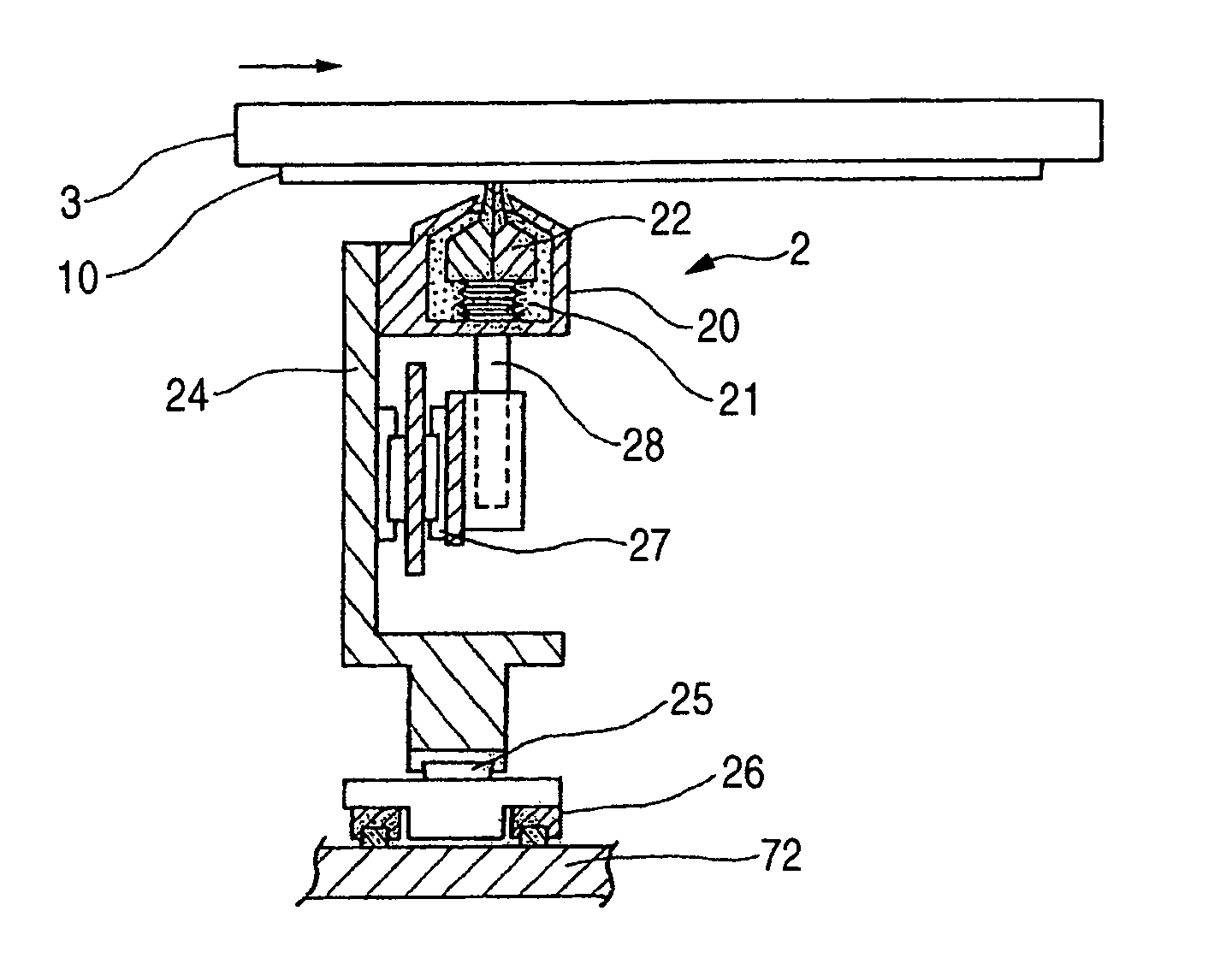
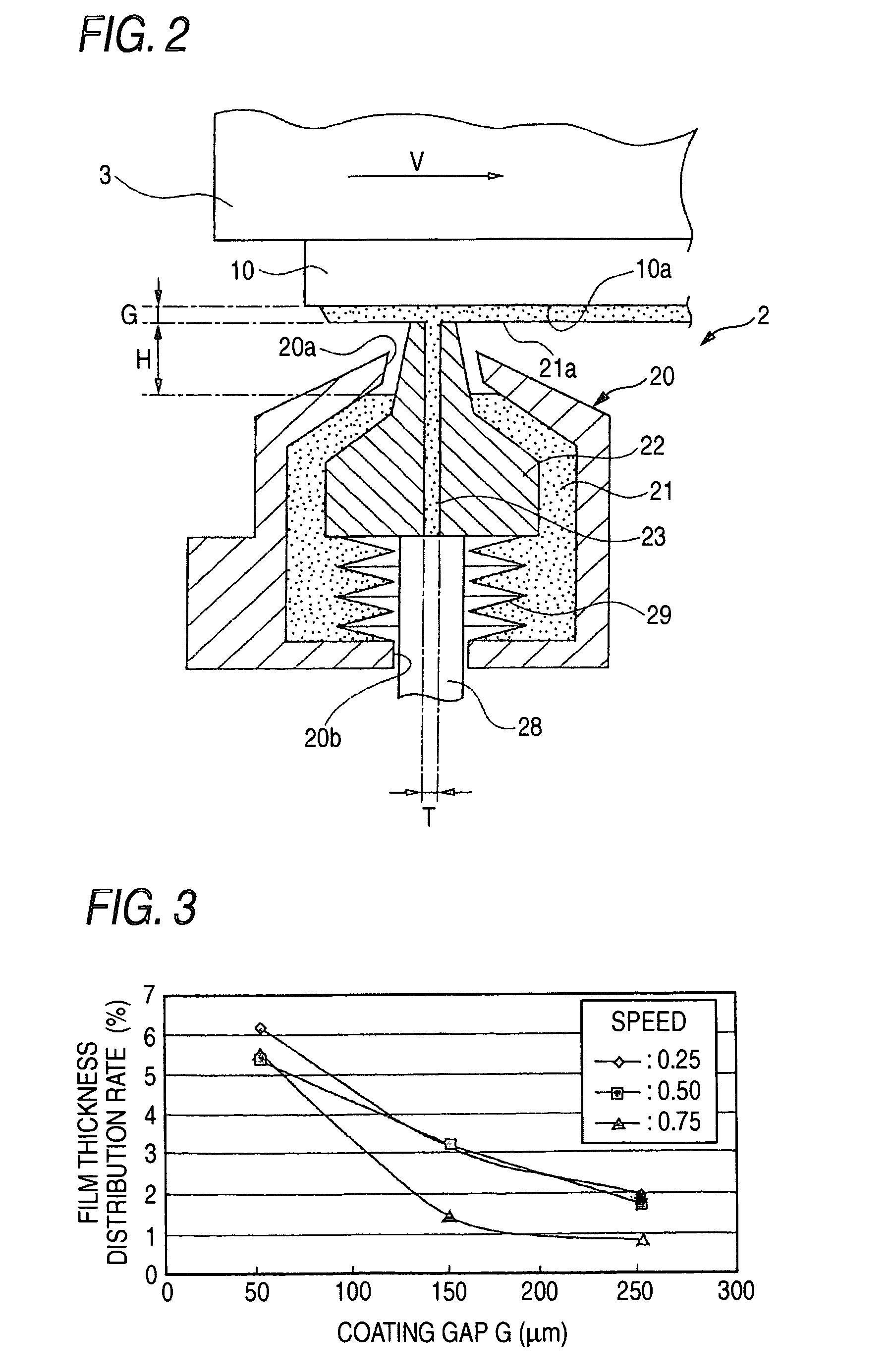
[0049]FIG. 2 is a cross-sectional view illustrating a state in which a coating operation is performed by a coating unit of a coating apparatus performing the method of manufacturing a substrate having a resist film according to the invention.

[0050]The method of manufacturing a substrate having a resist film according to the invention comprises the step of lifting liquid resist agent 21 stored in a liquid tank 20 by utilizing a capillary phenomenon caused in a slit-like capillary gap 23 of a coating nozzle 22, the step of downwardly directing a surface 10a of a substrate 10, which is to be coated, and causing this surface to move closer to the top portion of the coating nozzle 22, and the step of performing relative scan between the coating nozzle 22 and the surface 10a while causing the resist agent 21 raised by the coating nozzle 22 to wet the surface 10a through the top portion...


PUM

PropertyMeasurementUnit
lengthaaaaaaaaaa
thickness distribution rateaaaaaaaaaa

Abstract

The height H of a liquid level, a capillary gap distance T, and a relative scanning speed between a coating nozzle 22 and a surface 10a, which is to be coated, are adjusted within an adjustable range by simultaneously setting the thickness of a coating film 21a formed of a resist agent at a predetermined value. Thus, a coating gap G is widen.

Description

BACKGROUND OF THE INVENTION[0001]The present invention relates to a method of manufacturing a substrate provided with a resist film by coating a resist agent on a substrate to thereby form the resist film on the substrate and manufacture, for example, a photomask.[0002]Hitherto, there has been proposed a method of manufacturing a substrate provided with a resist film by coating onto a substrate a resist agent, which is used for forming a resist film, such as a photoresist, on a substrate, such as a silicon wafer, thereby to manufacture the substrate having the resist film. Also, a coating apparatus (or a coater) has been proposed as an apparatus for coating such a resist agent.[0003]What is called a spin coater is known as a conventional coating apparatus. This spin coater spreads a resist agent on a surface, which is to be coated, by the action of a centrifugal force by rotating this substrate in a horizontal plane at a high speed after liquid resist agent is dropped a central port...

Claims


Application Information

Patent Timeline
Patent Type & Authority Patents(United States)
IPC IPC(8): B05D1/18B05D1/26B05C5/00B05C5/02B05C9/00B05C9/02B05D1/32B05D7/00G03F7/16H01L21/027H05K3/00
CPCB05C5/0254G03F7/16B05C9/02H01L21/6715
Inventor MOTOMURA, SHUHOU
Owner HOYA CORP
Why Eureka
Try Eureka