Image recording apparatus, dynamic image processing apparatus, dynamic image reproduction apparatus, dynamic image recording apparatus, information recording / reproduction apparatus and methods employed therein, recording medium with computer program stored therein

a dynamic image processing and recording apparatus technology, applied in the field of image recording apparatus, can solve the problems of complex operation and inpractical recording, and achieve the effect of simplifying the operation

Inactive Publication Date: 2009-04-14
NIKON CORP
View PDF6 Cites 55 Cited by
  • Summary
  • Abstract
  • Description
  • Claims
  • Application Information

AI Technical Summary

Benefits of technology

[0045]A sixth object of the present invention is to simplify the op

Problems solved by technology

An 8 mm video cassette, which is a sequential access medium, i.e., a recording medium that does not allow random access, presents the following problems.(1) The problem described below typically arises when recording images on an 8 mm video cassette having image data recorded discretely on the tape.
In addition, there is a problem in that even when there are portions of the tape in which recording is possible, recording is not practically possible if these portions are discrete and in separate locations.(2) When reproducing an 8 mm video cassette in which, for instance, an unnecessary scene that the user does not wish to reproduce is recorded between scenes that the user wishes to reproduce continuously, the user must perform an operation such as a fast-forward during reproduction or the user must copy in advance the

Method used


Image

  • Image recording apparatus, dynamic image processing apparatus, dynamic image reproduction apparatus, dynamic image recording apparatus, information recording / reproduction apparatus and methods employed therein, recording medium with computer program stored therein
  • Image recording apparatus, dynamic image processing apparatus, dynamic image reproduction apparatus, dynamic image recording apparatus, information recording / reproduction apparatus and methods employed therein, recording medium with computer program stored therein
  • Image recording apparatus, dynamic image processing apparatus, dynamic image reproduction apparatus, dynamic image recording apparatus, information recording / reproduction apparatus and methods employed therein, recording medium with computer program stored therein

Examples


first embodiment

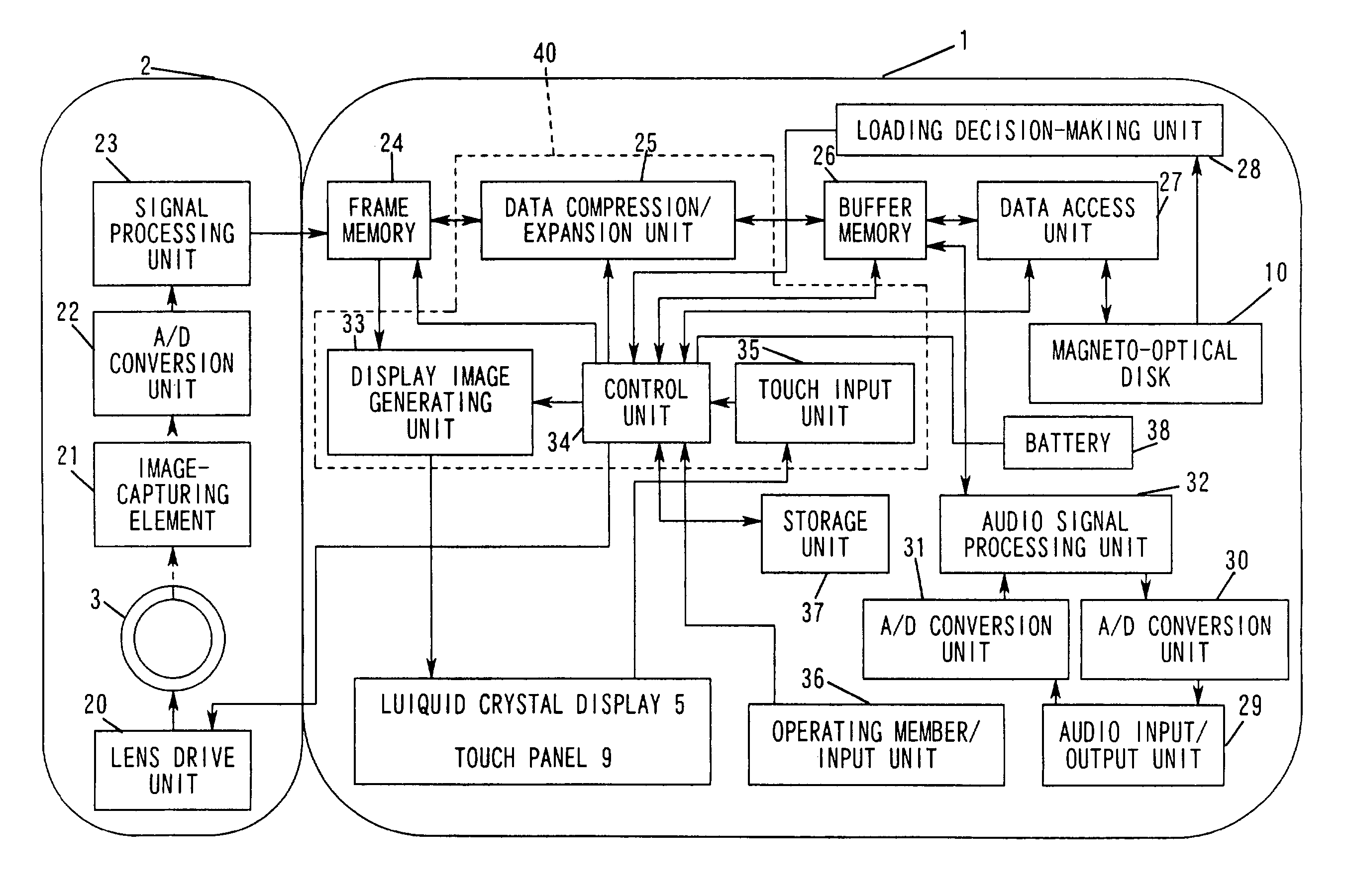
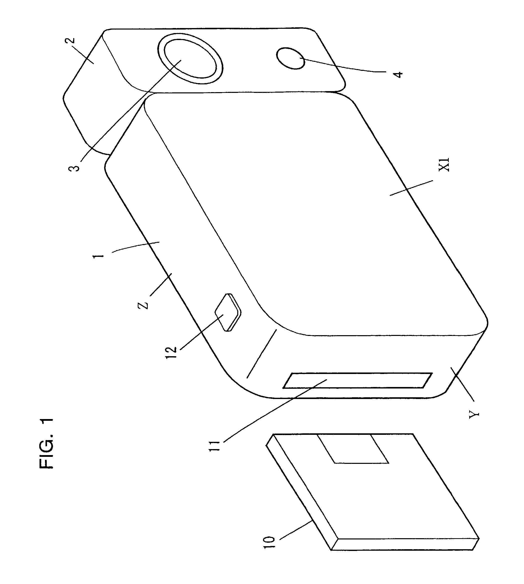
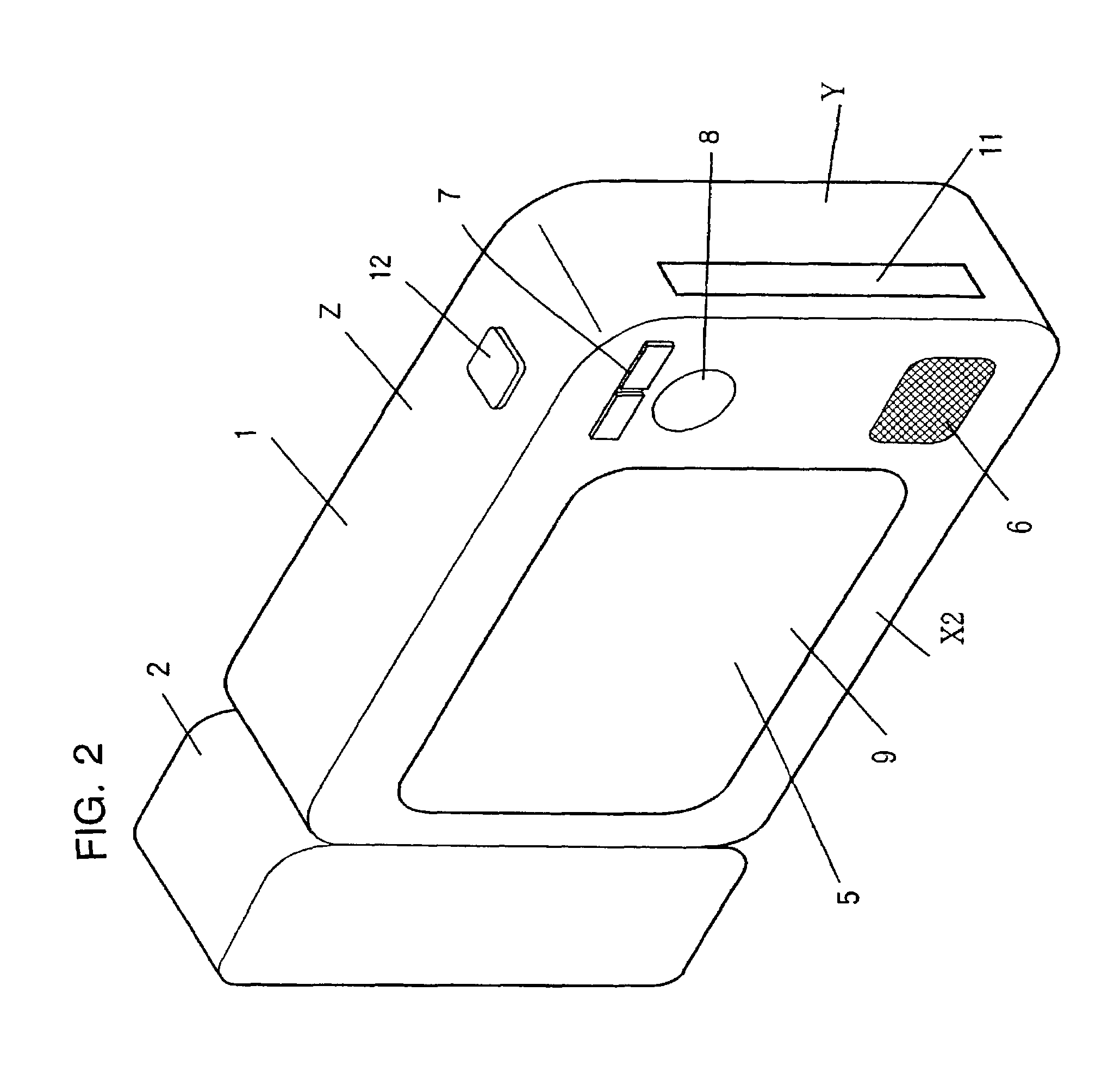
[0109]FIGS. 1 and 2 are perspectives showing the external structure of a video camera adopting the present invention. This video camera comprises a main body unit 1 and a camera unit 2. In the video camera, the surface positioned toward a subject when photographing the subject is referred to as a surface X1 and the surface positioned toward the user is referred to as a surface X2. At the surface X1 of the camera unit 2, an image-capturing lens 3 that takes in an optical image of the subject and a microphone 4 for collecting audio are provided. It is to be noted that the camera unit 2 is rotatably connected to the main body unit 1. As a result, the user is able to position the taking lens 3 in any direction while monitoring the image displayed on a liquid crystal display 5 (hereafter referred to as the LCD 5).

[0110]At the surface X2 of the main body unit 1, the LCD 5 that displays an image input from the image-capturing lens 3 or an image stored at a magneto-optical disk 10, a speake...

second embodiment

[0237]FIG. 24 is a perspective illustrating the external structure of a movie camera employing the information recording / reproduction apparatus according to the present invention. At the front surface of a main body 101, a liquid crystal display unit 104A is provided, with a touch panel 104B that outputs a positional signal corresponding to the position specified through a user touch operation mounted on the front surface of the liquid crystal display unit 104A. The touch panel 104B is constituted of a transparent material such as glass or resin so that the user can see images displayed on the liquid crystal display unit 104A formed inside the touch panel 104B via the touch panel 104B.

[0238]In addition, at the front surface of the main body 101, a power switch (main switch) 105, a dynamic image record button 106 for issuing an instruction for a start of dynamic image recording and a zoom button 108 which is operated when switching the zoom setting, are provided. At the upper surface...


PUM


Abstract

The image recording apparatus according to the present invention is provided with a conversion device that converts an optical image of a subject to an electrical signal, a recording circuit that records the electrical signal achieved through the conversion device in a storage device as image data and a display control circuit that detects an available capacity at the storage device and the length of time that power supply by a source is possible and displays them on a display as available capacity information and remaining power supply time information. The available capacity information indicates the length of available recording time remaining at the available capacity that has been detected.

Description

[0001]This is a Continuation of application Ser. No. 09 / 290,166 filed Apr. 13, 1999 now abandoned. The entire disclosure of the prior application is hereby incorporated by reference herein in its entirety.[0002]The disclosures of the following priority applications are herein incorporated by reference:[0003]Japanese Patent Application No. 10-102375, filed Apr. 14, 1998[0004]Japanese Patent Application No. 10-150178, filed May 29, 1998[0005]Japanese Patent Application No. 10-150179, filed May 29, 1998[0006]Japanese Patent Application No. 10-150180, filed May 29, 1998[0007]Japanese Patent Application No. 10-150181, filed May 29, 1998[0008]Japanese Patent Application No. 10-150182, filed May 29, 1998[0009]Japanese Patent Application No. 10-150183, filed May 29, 1998BACKGROUND OF THE INVENTION[0010](1) Field of the Invention[0011]The present invention relates to an image recording apparatus that displays the remaining recording capacity, a dynamic image processing apparatus that divides...

Claims


Application Information

Patent Timeline
IPC IPC(8): H04N5/91H04N5/00H04N7/26G11B27/034G11B27/10G11B27/34G11B27/36H04N1/00H04N1/21H04N5/77H04N5/783H04N5/85H04N9/804H04N9/82
CPCG11B27/034G11B27/105G11B27/34G11B27/36H04N1/00408H04N1/00477H04N1/00899H04N1/2112H04N5/772H04N1/2158G11B2220/20G11B2220/2525H04N1/00885H04N5/783H04N5/85H04N9/8042H04N9/8205H04N2101/00H04N2201/214G11B27/005H04N21/4436
Inventor JUEN, MASAHIROITO, MASAHARUNOZAKI, HIROTAKETANAKA, MASAHIDETOYODA, KENJI
Owner NIKON CORP
Why Eureka
Try Eureka