
Portable submersible cleaning device

a cleaning device and submerged technology, applied in the field of vacuum cleaning devices, can solve the problems of inconvenient use of suction type and education type cleaners, cumbersome vacuum head equipped with wheels, unbalanced brush strokes, etc., and achieve the effect of effectively removing angularly displaced debris, convenient introduction, and effective removal of displaced debris

Inactive Publication Date: 2009-04-21
AJELLO MIKE
View PDF6 Cites 40 Cited by
  • Summary
  • Abstract
  • Description
  • Claims
  • Application Information

AI Technical Summary

Benefits of technology

[0016]The housing further includes first and second chambers in fluid communication with each other. Such a first chamber is advantageously seated below the second chamber, and is detachable from the housing. The first chamber is effectively bifurcated into threadably engaged top and bottom halves such that the first chamber is selectively removable from the housing. Such a second chamber is monolithically defined within the housing and is in direct electrical communication with the receptacle. The access door is positioned about the first chamber for advantageously allowing a user to conveniently remove the first chamber as needed.
[0017]The cleaning head includes an intake port advantageously disposed above a bottom edge of the cleaning head. A rectilinear axle penetrates through oppositely faced beveled walls of the intake port and has opposed ends removably attached to the cleaning head. Such an axle passes through the bottom end of the housing such that the cleaning head is effectively articulated along a fulcrum axis defined along the axle for advantageously allowing the cleaning head to contact uneven surfaces during operating conditions.
[0019]The inhaling mechanism includes a fiber filter removably nested within the first chamber for effectively removing angularly displaced debris from the debris-saturated water. Such a fiber filter has an axial bore formed therein such that proximal and distal ends of the axial bore are advantageously disposed adjacent to proximal and distal ends of the first chamber respectively. A one-way check valve is selectively pivotal between open and closed positions such that the debris-saturated water is conveniently introduced through the distal end of the bore and effectively permitted to flow through the bore of the fiber filter. A sponge gasket is connected to the proximal end of the first chamber and is contiguously engaged directly with the proximal end of the bore such that the fluid is effectively prohibited from being laterally displaced along an outer surface of the fiber filter.
[0020]The inhaling mechanism further includes a power motor electrically coupled to a power source housed within the receptacle. Such a motor includes a driveshaft and an impeller statically mounted to a distal end of the driveshaft. Such an impeller is axially aligned directly above the proximal end of the first chamber. The motor effectively causes the driveshaft and the impeller to simultaneously rotate along a rotational path and thereby advantageously create an upward vortex along which the debris-saturated water is angularly displaced and conveniently introduced through the bore. The motor is advantageously located within the second chamber and upstream of the fiber filter. The motor further includes a plurality of slits formed within an outer wall thereof. The housing includes a plurality of slits formed therein and cooperating with the motor slits in such a manner that the clean water is continuously discharged out from the second chamber after the debris is angularly filtered in the first chamber.
[0021]The device further includes a first anchored conduit fixedly coupled directly to the top opening of the proximal end of the housing. A plurality of auxiliary shafts is removably connected to the anchored conduit, wherein one of the auxiliary shafts is provided with a plurality of tie straps for conveniently maintaining the auxiliary shafts grouped together during non-operating conditions. Such auxiliary shafts are selectively connectable along an end-to-end connection respectively for effectively assisting a user to access hard to reach target zones within the aqueous environment.

Problems solved by technology

These manual pool cleansers have several drawbacks when used to clean spas.
The vacuum heads equipped with wheels are too cumbersome, even when flexible, to efficiently clean smaller and more contoured surfaces.
This tends to result in unbalanced brush strokes.
Both the suction type and the education type cleaners are inconvenient to use when they must be removed from the pool water.
When an education-type vacuum head is used, the user runs the risk of being sprayed by the discharge of the pressurized water each time the head is removed from the pool water.
However, when cleaning shallow surfaces, the discharge port of an education type vacuum head may frequently be inadvertently removed from the water, thus spraying the user.
The efficiency of the filter cartridge allows for the use of a small motor and small battery which, in turn, result in the small size of the vacuum cleaner.
Unfortunately, this prior art example requires the use of a power cord which can be cumbersome and limit the effective range of the device, and an AC power source must be readily available for use.
In addition, this example poses a risk of electrocution of a user or other person nearby during operating conditions.

Method used


Image

  • Portable submersible cleaning device
  • Portable submersible cleaning device
  • Portable submersible cleaning device

Examples


Embodiment Construction

[0034]The present invention will now be described more fully hereinafter with reference to the accompanying drawings, in which a preferred embodiment of the invention is shown. This invention may, however, be embodied in many different forms and should not be construed as limited to the embodiment set forth herein. Rather, this embodiment is provided so that this application will be thorough and complete, and will fully convey the true scope of the invention to those skilled in the art. Like numbers refer to like elements throughout the figures.

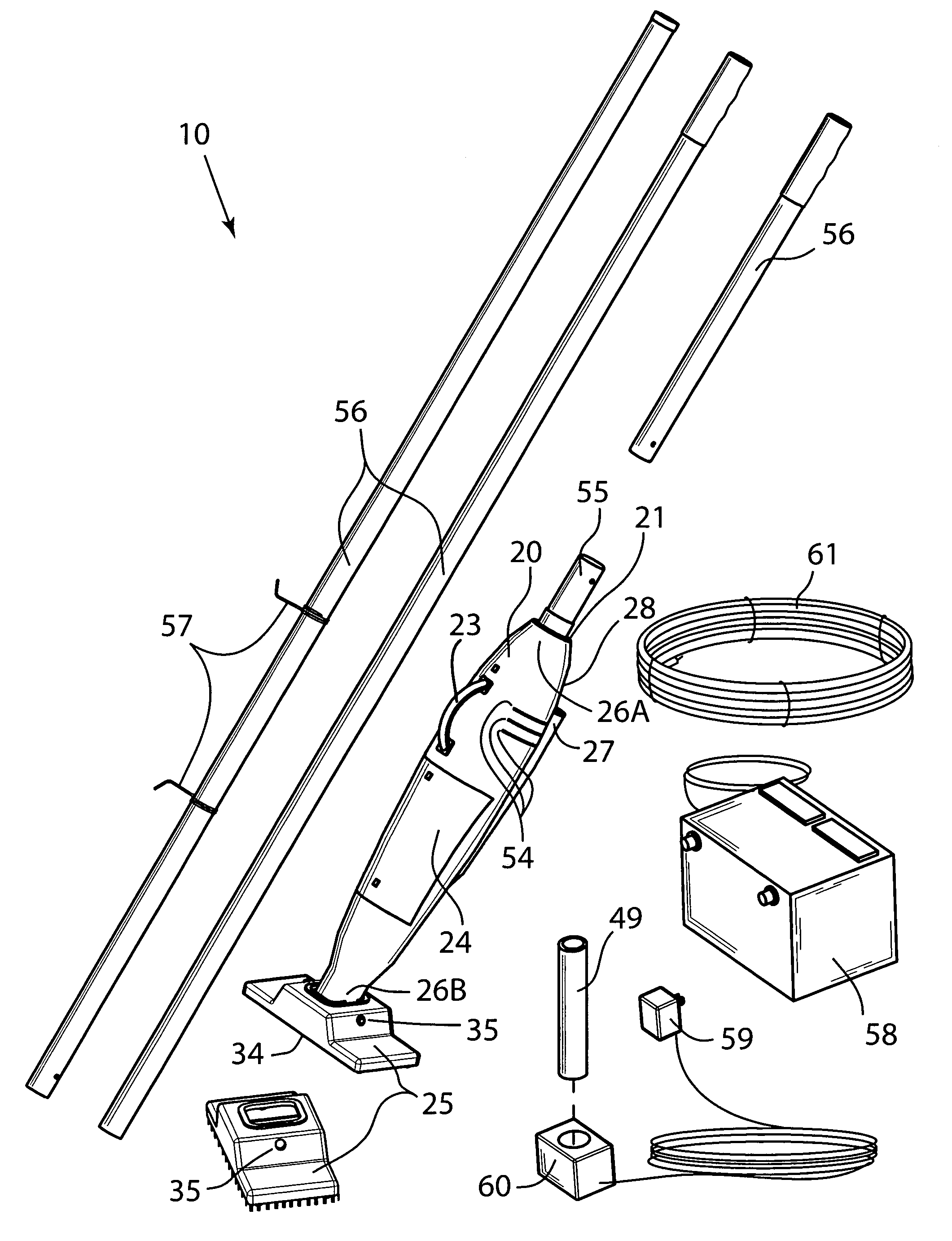
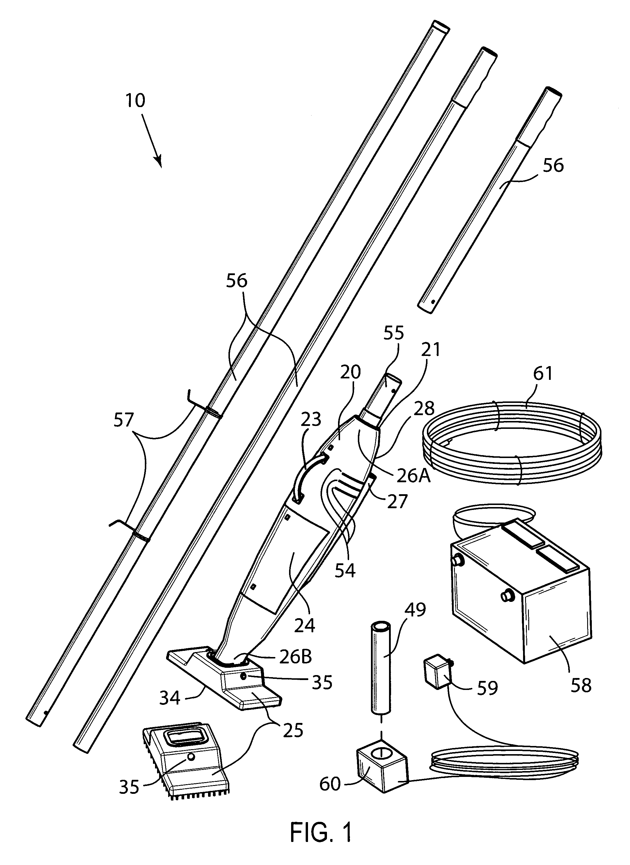
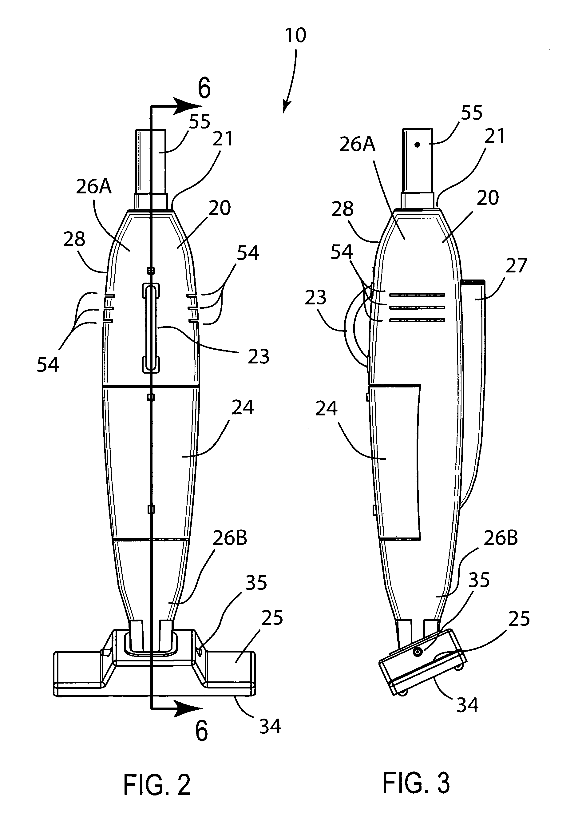
[0035]The device of this invention is referred to generally in FIGS. 1-8 by the reference numeral 10 and is intended to provide a portable submersible cleaning device. It should be understood that the device 10 may be used to clean many different types of aqueous environments and should not be limited to cleaning only those aqueous environments described herein.

[0036]Referring initially to FIGS. 1, 2, 3, 4, 5 and 6, the device 10 includes a h...


PUM


Abstract

A portable submersible cleaning device includes a housing that has axillary opposed top and bottom apertures. The housing has a frusto-conical shape, and includes a handle and an access door removably attached thereto. A cleaning head is pivotally and removably attached to a distal end of the housing, and an exterior receptacle is abutted to an outer surface thereof. A mechanism inhales a predetermined volume of debris-saturated water upwardly through the cleaning head and along a unidirectional passageway such that debris is extracted from the debris-saturated water while clean water is expelled outwardly from the housing and reintroduced into the aqueous environment. The exterior receptacle is isolated from the aqueous environment such that power is transmitted to the inhaling mechanism while the housing is submerged beneath a water line of the aqueous environment.

Description

CROSS REFERENCE TO RELATED APPLICATIONS[0001]This application claims the benefit of U.S. Provisional application Ser. No. 60 / 732,213, filed Nov. 2, 2005.BACKGROUND OF THE INVENTION[0002]1. Technical Field[0003]This invention relates to vacuum cleaning devices and, more particularly, to a portable submersible cleaning device for removing debris from aqueous environments such as pools, spas and like bodies of water.[0004]2. Prior Art[0005]Pool cleaners vary widely in degree of sophistication. Existing products range from simple brushes to automatic cleaners with self-propelled vacuum heads. In many designs, the pool's circulation system is used to create the vacuum at the vacuum head in addition to filtering the influent water. In others, the vacuum may be created by applying pressurized water to the device and a filter may be contained on the vacuum head.[0006]An efficient cleaning method provided for a water powered vacuum so that dirt particles will be removed from the pool at the ...

Claims


Application Information

Patent Timeline
IPC IPC(8): E04H4/16
CPCE04H4/1636
Inventor AJELLO, MIKE
Owner AJELLO MIKE
Learn More