Method and apparatus for indicating a load

a technology of load indicator and fastener, which is applied in the direction of measuring torque/twisting force while tightening, fastening means, instruments, etc., can solve the problems of increasing the maximum break point of the load indicator, reducing the degree of clearance required, and achieving the proper tightness of the fastener (tension) and maintaining this tightness once the system is placed in service. , to achieve the effect of reducing the range of movement and reducing the degree of clearan

Active Publication Date: 2009-04-21
VALLEY FORGE & BOLT MFG +1
View PDF20 Cites 12 Cited by
  • Summary
  • Abstract
  • Description
  • Claims
  • Application Information

AI Technical Summary

Benefits of technology

[0017]Use of two levers to shift part of the amplified response to the second lever reduces the range of movement of the first lever within the fastener bore reducing the degree of clearance required for the first lever. Any number of levers may be used to achieve the desired amplification in a given application. This significantly reduces the depth of the broader section of the fastener bore required to accommodate the amplified response. Additional advantages afforded by the present invention include increased sensitivity of the load indicator, a reduction in the overall length of load indicator and in the depth of the bore.

Problems solved by technology

In many applications, achieving the proper fastener tightness (tension) and maintaining this tightness once the system is placed in service is problematic.
Monitoring the load on a fastener during installation and service is equally problematic.
As the fastener is tightened, this load increases to a maximum break point i.e. where the fastener yields, breaks, or its integrity is otherwise compromised.
The loss of tension that results from these occurrences can cause misalignment or premature wear in the assembly, leakage (in applications where the fastener is used for sealing), or catastrophic joint failure due to excessively high loads on other members of the assembly.
Because current fasteners do not reliably indicate the status of the tension in the fastener, users must often use cumbersome methods to check the tightness of each bolt, or simply retighten all of the fasteners regardless of whether such re-tightening is needed.
The retorquing (i.e. tightening) of a fastener, however, induces wear and strain in the fastener system from corrosion, friction, variations in nut condition, torque values, and the like.
Thus, such visual load indicators are typically only available in larger fasteners or in fasteners having enlarged heads.
For example, electronic or ultrasonic methods for determining existing clamp load require experienced operators, expensive equipment, clean surfaces and records of pre-installation test values for each bolt or stud.
Moreover, devices that require complicated electronics tend to add to the expense, maintenance and unreliability of the system.
In addition, such systems may be adversely affected by shock and other extreme conditions.
These systems generally require skilled labor to use complicated and sophisticated measurement techniques.
Additionally, the reference surfaces generally are exposed to the outside environment which often leads to outside forces affecting the system.
Determination of intermediate load levels, or partial loosening of a fastener, is not possible.
Furthermore, because most fasteners are in-service in an outdoor environment, variations in sunlight may restrict an inspector's ability to determine the specific color of the indicator.
While this device has some utility in certain applications, over time, the device can become inaccurate and lose calibration.
This loss of calibration has been found to be inherent in the design of the U-shaped sensing element, because as the element is continually strained, its calibration characteristics are inherently affected.
In addition, temperature may affect the bending characteristics of this U-shaped element.
Also, when attempting to match coefficients of linear expansion between the bolt and the U-shaped element, one is limited due to the fact that only a limited number of materials are sufficiently resilient to be used for this design.
The bottom of the U is in constant contact with the abutment and any shock will be transferred at the bottom of the U and tend to deform the U-shaped element causing it to lose calibration.
Due to the design of this system, and the complex arrangement of the levers, and position of the indicator window, the indicator components must be positioned on the outside of the bolt, which in some applications is not possible due to space restrictions.
In cases where it is possible to use such a configuration, the elements of the instrument may be susceptible to outside forces and damage.
Upon damage, no convenient method exists to verify whether or not the unit is still calibrated.
Thus, a need exists for a visual load indicator that may be used with smaller and more conventional fastener configurations in addition to overcoming the shortcomings of prior art apparatuses and methods that are time consuming, skilled labor intensive, extend outside the fastener, subject to environmental conditions, unreliable, or inoperable at high temperatures and require expensive measuring equipment.

Method used


Image

  • Method and apparatus for indicating a load
  • Method and apparatus for indicating a load
  • Method and apparatus for indicating a load

Examples


Embodiment Construction

[0028]The following description is of exemplary embodiments of the invention only, and is not intended to limit the scope, applicability or configuration of the invention. Rather, the following description is intended to provide a convenient illustration for implementing various embodiments of the invention. As will become apparent, various changes may be made in the function and arrangement of the elements described in these embodiments without departing from the scope of the invention as set forth herein. It should be appreciated that the description herein may be adapted to be employed with alternatively configured devices having different shapes, components, and the like and still fall within the scope of the present invention. Thus, the detailed description herein is presented for purposes of illustration only and not of limitation.

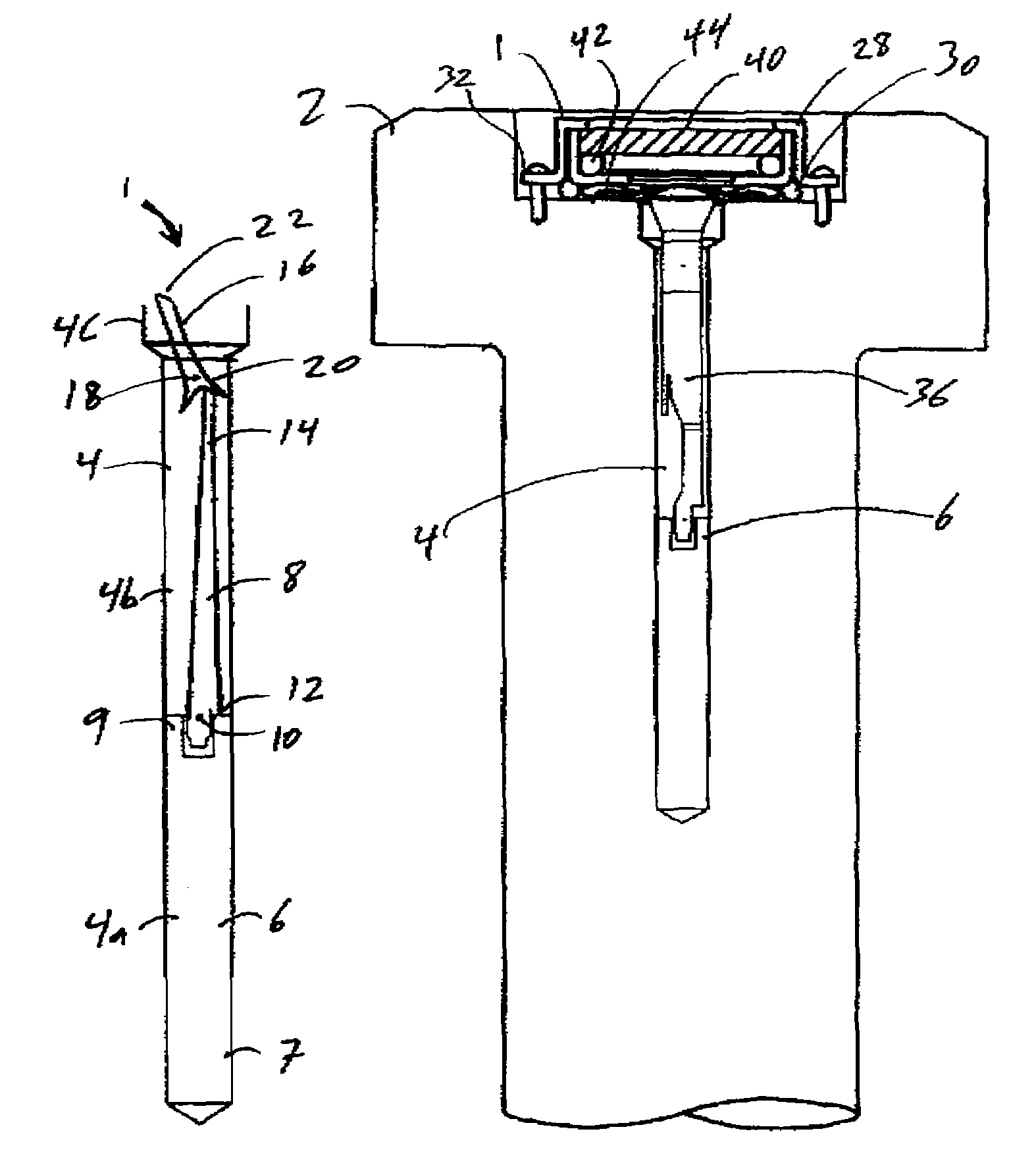
[0029]In accordance with various aspects of the present invention, a fastener includes a central bore for receiving a load indicating assembly or “c...


PUM


Abstract

A load indicating insert visually displays fastener loading during tightening and use of a fastener. First and second levers are positioned by a connective cartridge substantially within a fastener bore to provide a compound. amplified indication of loading as a function of the elongation or deformation of the fastener. The first lever is connected at an internal pivot point of a cartridge with a lower end resting on an abutment within the fastener bore. As the abutment moves the first lever during elongation, the second lever moves relative to a visual loading scale. As the fastener is loaded and unloaded, varying elongation of the fastener causes displacement of the abutment and movement of the indicator back and forth along the load indicating scale.

Description

FIELD OF INVENTION[0001]This invention generally relates to a load indicating fastener, and more particularly, to an apparatus and method for visually representing the tensile strain in a fastener.BACKGROUND OF THE INVENTION[0002]Fasteners are used in a wide variety of applications, such as motors, railroad tracks, flange assemblies, petrochemical lines, foundations, mills, drag lines, power turbines and studs on cranes and tractors. In many applications, achieving the proper fastener tightness (tension) and maintaining this tightness once the system is placed in service is problematic. Monitoring the load on a fastener during installation and service is equally problematic. As is known in the use of such fasteners, as force is applied to a portion of the fastener, e.g., a head of a bolt or the like, the fastener is elongated. As the fastener is tightened, this load increases to a maximum break point i.e. where the fastener yields, breaks, or its integrity is otherwise compromised.[...

Claims


Application Information

Patent Timeline
Patent Type & Authority Patents(United States)
IPC IPC(8): F16B31/02
CPCF16B31/025G01L5/24F16B31/02G01D13/28
Inventor CLARKE, RONALD C.
Owner VALLEY FORGE & BOLT MFG
Why Eureka
Try Eureka