Stacking-type, multi-flow, heat exchanger

a heat exchanger and multi-flow technology, applied in indirect heat exchangers, laminated elements, lighting and heating apparatuses, etc., can solve the problems of insufficient brazing strength and improper connection of respective parts, and achieve high degree of accuracy in position, sufficient bonding strength, and high degree of accuracy

Inactive Publication Date: 2009-04-21
SANDEN CORP
View PDF34 Cites 6 Cited by
  • Summary
  • Abstract
  • Description
  • Claims
  • Application Information

AI Technical Summary

Benefits of technology

[0011]Accordingly, it is an object of the present invention to provide improved structures of and methods for manufacturing stacking-type, multi-flow, heat exchangers, and especially, high-performance, stacking-type, multi-flow, heat exchangers, which may achieve a high degree of accuracy in the assembly of an end plate and various parts, and which may achieve a desirable connection of respective parts with both a high degree of accuracy in position and sufficient bonding strength, at a low cost.
[0013]In such a stacking-type, multi-flow, heat exchanger, because the engaging portion, which engages the raised portion of the outermost tube plate, is provided integrally to the end plate, the end plate may be readily positioned relative to the outermost tube plate with a high degree of accuracy, and may be temporarily secured surely for a proper assembly. Therefore, because a positional shift of the end plate during the temporary assembly may be reduced or prevented, the brazing properties (e.g., the brazing accuracy) of the end plate and, ultimately, of the respective parts, may be enhanced. Such an engaging function may be readily achieved by a combination of the raised portion and a hole provided on the end plate engaging the raised portion.
[0014]Further, because the closing portion, which closes the opening of the raised portion, is provided integrally to the end plate, the opening of the raised portion may be closed readily and certainly by setting the end plate. Further, because the periphery of the raised portion and the inner circumferential edge of the hole of the end plate and the end surface of the raised portion and the end plate may be more securely brazed, the brazing area between the end plate and the outermost tube plate may be enlarged, and the strength of the braze between both members may be increased. Such a closing function may be readily achieved by providing a lid to the end plate for closing the opening of the raised portion.
[0016]Further, the above-described end plate, having the hole for engaging the raised portion and the extended portion for forming the lid closing the opening of the raised portion, may be readily manufactured by a single process, such as pressing, stamping, or the like. Therefore, in the present invention, the number of parts and the number of processes, may not be increased substantially, and the cost for the manufacture may be reduced or prevented for rising.
[0017]Moreover, if the lid is formed to have a portion protruded from a position of the raised portion, the strength of the lid may be increased. Further, if the degree of protrusion of the protruded portion is set, so that an outer surface of the protruded portion and an outer surface of a portion of the end plate connected to an outermost fin are formed to be substantially flush, the temporarily assembled heat exchanger may be securely fixed by using a simple jig for brazing. Therefore, the brazing property may be significantly improved.
[0018]Thus, in the stacking-type, multi-flow, heat exchanger, according to the present invention, because the engaging portion and the closing portion are provided integrally to the end plate for engaging the raised portion of the outermost tube plate and for closing the opening of the raised portion (i.e., for closing an end of a tank), the end plate and, ultimately, the entire heat exchanger, may be assembled temporarily at a proper position with a high degree of accuracy, and the brazing properties may be significantly improved. Further, by providing the closing portion integrally to the end plate, increases in the number of the parts and the number of processes may be substantially prevented. This may contribute to lowering costs or reducing or eliminating cost increases.

Problems solved by technology

Consequently, the respective parts may not be connected properly.
In such a structure, however, because it is difficult to ensure a sufficiently large area for brazing between projecting portion 125 of end plate 124 and raised portion 122 of projecting portion 121 of outermost tube plate 119, insufficient brazing strength may be achieved.

Method used


Image

  • Stacking-type, multi-flow, heat exchanger
  • Stacking-type, multi-flow, heat exchanger
  • Stacking-type, multi-flow, heat exchanger

Examples


first embodiment

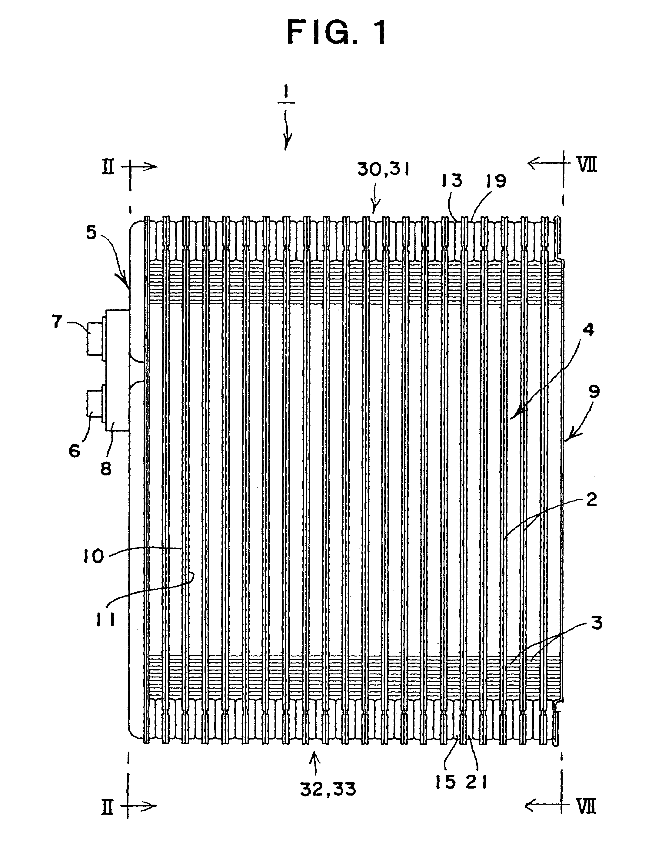
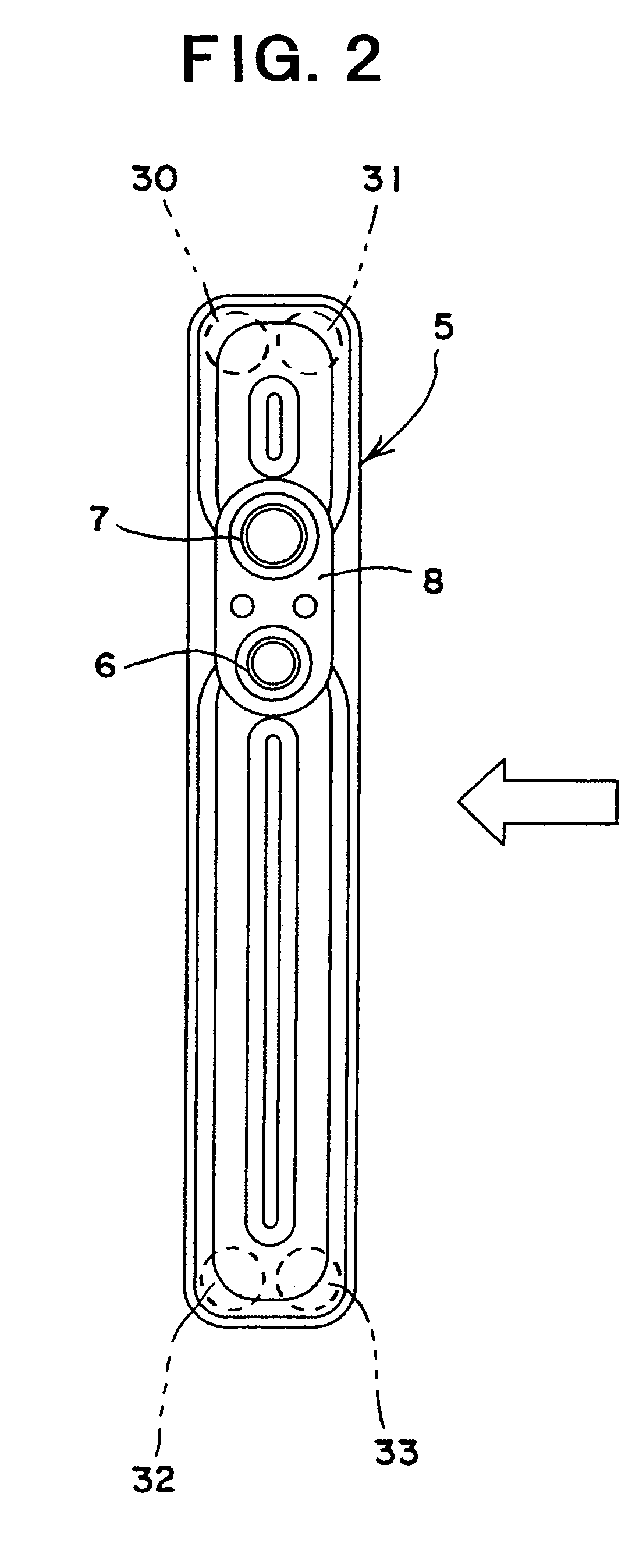
[0046]Referring to FIGS. 1-7, a heat exchanger is depicted according to the present invention. Heat exchanger 1 is constructed as a stacking-type, multi-flow, heat exchanger. As depicted, heat exchanger 1 comprises a heat exchanger core 4 formed by a plurality of heat transfer tubes 2 and a plurality of outer fins 3 stacked alternately. A side tank 5 is connected to one end of heat exchanger core 4 in the stacking direction, and introduction / discharge passages of a heat exchange medium (e.g., refrigerant) into / from the heat exchanger are formed in the side tank 5. A flange 8 having an inlet 6 and an outlet 7 for heat exchange medium is connected to side tank 5. An end plate 9 is connected to the other end of heat exchanger core 4 in the stacking direction.

[0047]As depicted in FIGS. 3 and 5, each heat transfer tube 2 is formed by connecting a pair of tube plates 10 and 11 (i.e., a first tube plate 10 and a second tube plate 11) to each other at their outer circumferential portions. P...

third embodiment

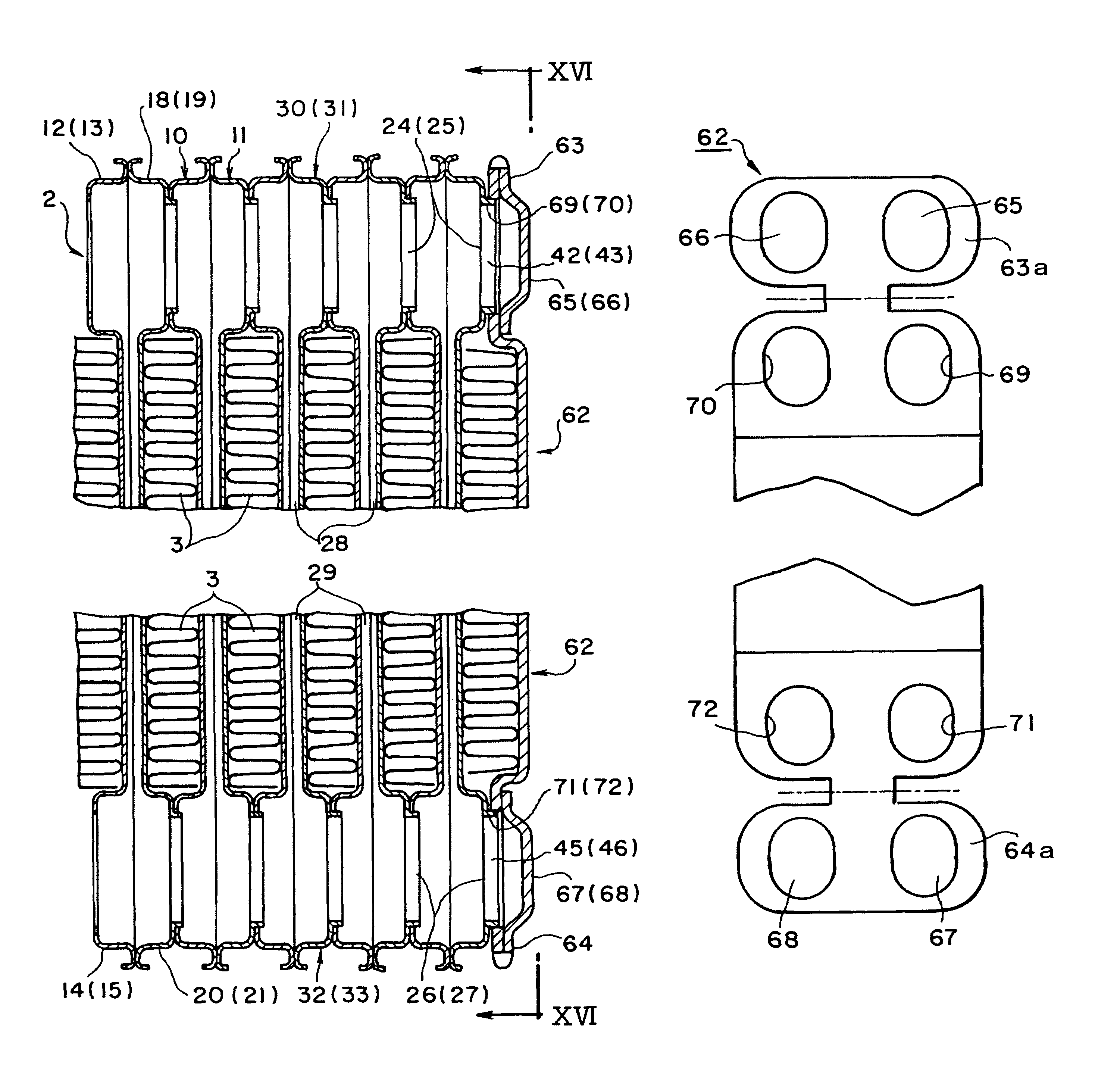
[0059]FIGS. 13 to 16 depict a stacking-type, multi-flow, heat exchanger and the method for manufacturing such a heat exchanger, according to the present invention. In this embodiment, as depicted in FIG. 14, lid forming portions 63a and 64a are formed integrally with end plate 62 at both end portions of end plate 62 in its longitudinal direction. Protruded portions 65, 66, 67, and 68 are formed on lid forming portions 63a and 64a, respectively. As depicted in FIGS. 15A and 15B, by turning back lid forming portions 63a and 64a, lids 63 and 64 are formed, and the lids 63 and 64 cover holes 69, 70, 71, and 72 provided on end plate 62, respectively, as depicted in FIG. 16.

[0060]Moreover, in this embodiment, because raised portions 24, 25, 26, and 27 of second tube plate 11 are inserted into holes 69, 70, 71, and 72 of end plate 62, respectively, end plate 62 may be positioned with a high degree of accuracy similar to that in the first embodiment, and the brazing properties may be improv...


PUM

PropertyMeasurementUnit
timeaaaaaaaaaa
brazing strengthaaaaaaaaaa
bonding strengthaaaaaaaaaa

Abstract

A stacking-type, multi-flow, heat exchanger includes a plurality of heat transfer tubes and fins stacked alternately, a tank formed at an end of the heat transfer tubes, and an end plate provided at an end of the tank. The heat exchanger has a projecting portion provided to a surface of an outermost tube plate, a raised portion with an opening formed through the projecting portion, and an engaging portion and a closing portion provided integrally to the end plate for engaging the raised portion and for closing an opening of the raised portion. A positional shift of the end plate at the time of temporary assembling may be prevented, and the brazing properties and the pressure resistance of the tank end portion may be increased.

Description

BACKGROUND OF THE INVENTION[0001]This application claims the benefit of Japanese Patent Application No. 2004-30804, filed Feb. 6, 2004, which is incorporated herein by reference.[0002]1. Field of the Invention[0003]The present invention relates to a stacking-type, multi-flow, heat exchanger comprising an end plate connected to an outermost layer of a heat exchanger core formed by stacking heat transfer tubes and fins alternately, and to methods for manufacturing such heat exchangers. Specifically, the present invention relates to an improved structure of a stacking-type, multi-flow, heat exchanger suitable as a heat exchanger for use in an air conditioner, in particular, for vehicles.[0004]2. Description Related Art[0005]A stacking-type, multi-flow, heat exchanger having alternately stacked heat transfer tubes and fins is known in the art, for example, as a heat exchanger having a structure shown in FIGS. 22 and 23 (as shown in Japanese Utility Model Laid-Open No. 7-12778). In FIGS....

Claims


Application Information

Patent Timeline
Patent Type & Authority Patents(United States)
IPC IPC(8): F28D1/03F28F3/00F28F9/02
CPCF28D1/0333F28F9/0202Y10T29/49389F28F2280/04
Inventor OHNO, TAKAYUKI
Owner SANDEN CORP
Why Eureka
Try Eureka