Combination acoustic diffuser and absorber and method of production thereof

a technology of acoustic absorbers and diffusers, which is applied in the field of acoustic room treatments, can solve the problems of reducing the diffusion performance of diffusers, reducing the cost of assembly of discrete pieces and subsequent sealing of the resulting assembly, and reducing the efficiency of acoustic absorption. the effect of cost-effectiveness, convenient production and convenient us

Inactive Publication Date: 2009-04-21
GUDIM WILLIAM ORLIN
View PDF27 Cites 34 Cited by
  • Summary
  • Abstract
  • Description
  • Claims
  • Application Information

AI Technical Summary

Problems solved by technology

A notable drawback of many existing reflection phase grating diffusers is that they are constructed from discrete pieces joined to each other, which construction method requires the sealing of these joints to ensure that sound does not “leak” out of the wells, which effect can result in the absorption of the leaked acoustic energy and therefore degrade the diffusion performance of the diffuser.
Assembly of discrete pieces and subsequent sealing of the resulting assembly are expensive processes, and a diffuser having a monolithic acoustically reflective diffusing surface is therefore desired.
A drawback of this approach is that the absorption characteristics of the Helmholtz resonator absorbers are not adjustable by a user thereof.
Another drawback of this approach is that the efficiency of the otherwise reflective diffusing surface can decrease as it is perforated and thus has its reflective surface area reduced.
As residential environments are often occupied, and may contain children, the device should not introduce or require introduction into that environment of any substances that with repeated long-term exposure may be deleterious to human health.
The light-duty construction methods and materials employed in the building of the typical residential environment impose particular design constraints upon devices intended for attachment thereto.
The local magnitude of the acoustic pressure can pose a problem if it contributes to a perceived excess of sound energy of a particular frequency at the position of the listener, relative to the contribution of that frequency to the overall source program.
This situation will contribute to the perception of an excess of acoustic energy at the odd harmonics at 0.50 fractional room height, which is an unacceptable result as judged by the articulated performance criterion of faithful and accurate acoustical reproduction within the listening room of the source signal.
This unacceptable result is exacerbated by the fact that distortion products formed when reproduction of the fundamental tone is attempted often appear as acoustic energy at odd-order harmonics of that fundamental.
Further, it is difficult to remediate this undesirable difference between the acoustic energy levels at the fundamental frequency and odd-order harmonic frequencies by changing listening position, as it is often not possible or practical for a listener to change position along the vertical axis of the room, unlike along the two horizontal axes of the room, in order to receive an acoustical energy density distribution that more accurately reflects that energy distribution in the original source.
Further yet, because typical residential listening environments tend to have low ceiling heights of approximately 96 inches, without further acoustic treatment there will tend to be strong early reflections from both ceiling and floor.
While a certain amount of sound absorption in a listening environment can be desirable, notably to reduce the sound energy level at particular positions within the room at which they may be elevated due to room configuration, absorption reduces the total amount of acoustic energy within the listening environment, a phenomenon which may have its own undesirable effects.
Since multiple reflecting surfaces must be nestable, and since each reflecting surface will have the same irregular surface topology, that surface topology should be one where the walls of the contemplated wells are not oriented at right angles to the area of the diffuser, as this would not permit the nesting of multiple identical reflecting surfaces.

Method used


Image

  • Combination acoustic diffuser and absorber and method of production thereof
  • Combination acoustic diffuser and absorber and method of production thereof
  • Combination acoustic diffuser and absorber and method of production thereof

Examples


Embodiment Construction

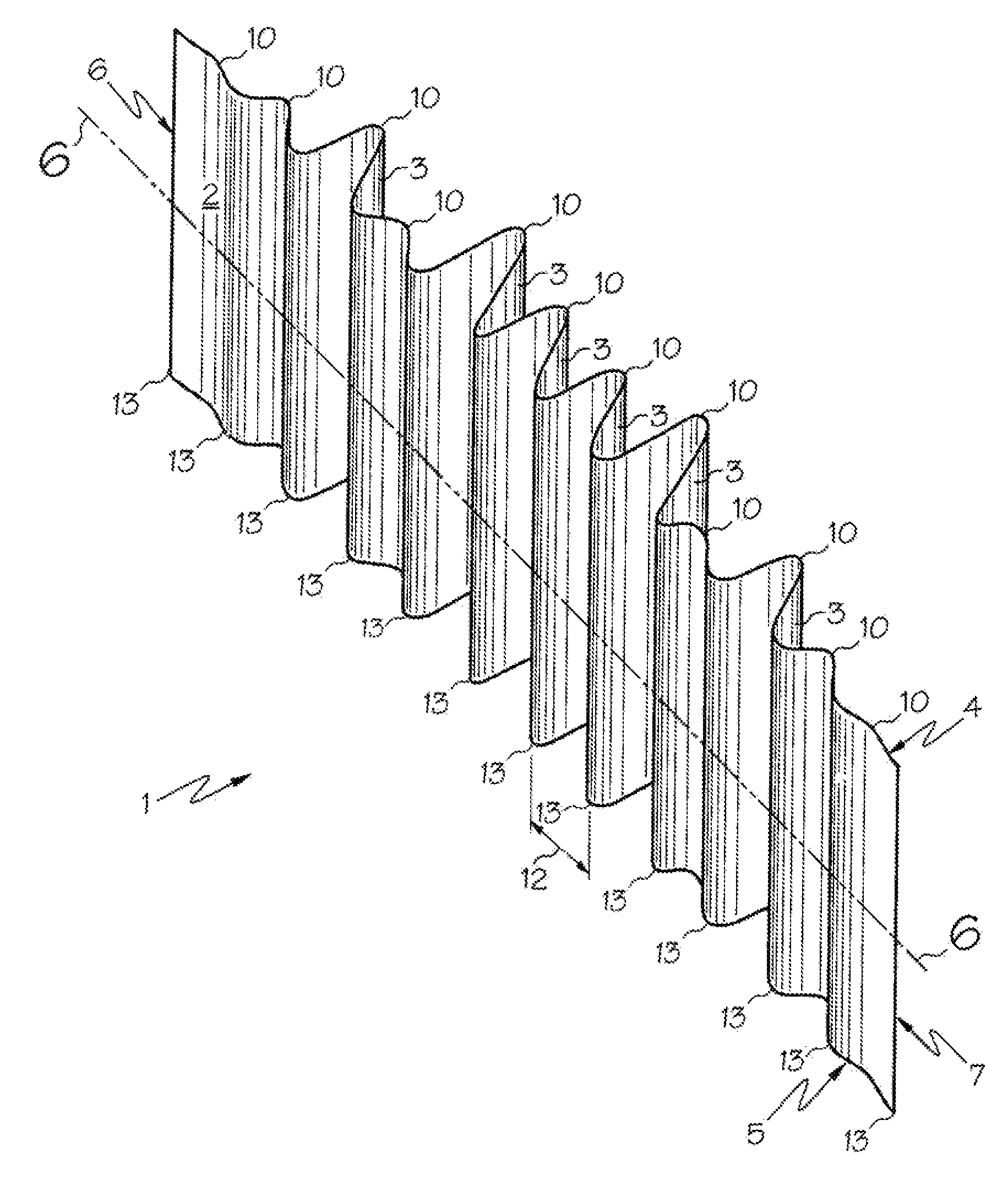
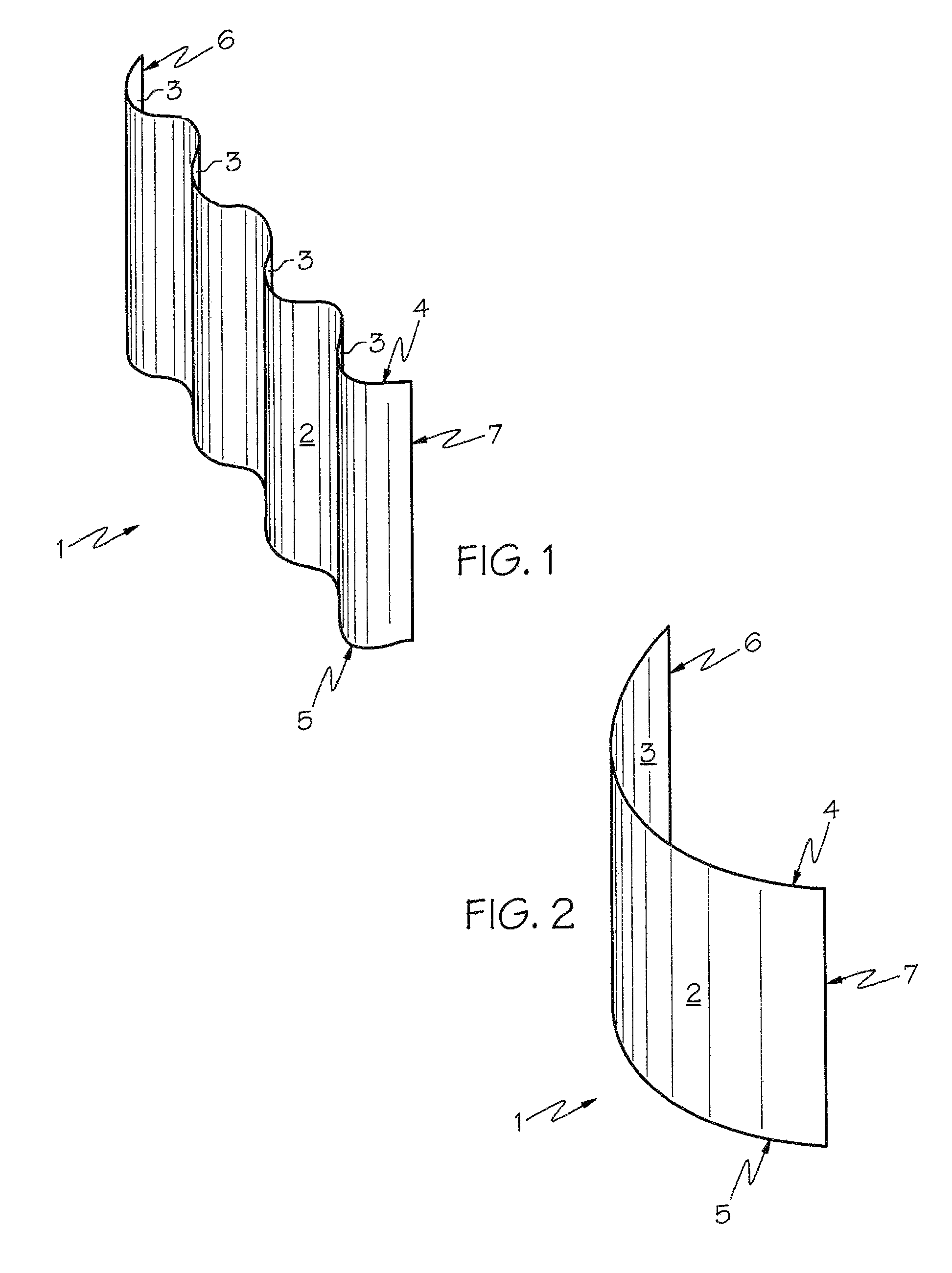
[0036]Referring now to the drawings, and particularly to FIG. 1 thereof, an embodiment of a curved acoustically reflective diffusing surface 1 is shown, constructed from wood. The curved diffusing surface 1 has a front face 2, a rear face 3, a top edge 4, a bottom edge 5, a left edge 6 and a right edge 7. The topology of the curved diffusing surface 1 can be corrugated as depicted in FIG. 1, or can be based on a single continuous curve such as the arc of a circle, as depicted in FIG. 2, both of which implementations will diffuse the acoustic energy incident upon the surface in a horizontal hemidisk extending the height of the diffusing surface, or more generally as is known in the art, “one-dimensionally”. The overall height of the curved acoustically reflective diffusing surface 1 in FIGS. 1 and 2 is optimally 32 inches, which height permits the hemidisk of diffusion to occupy the middle vertical third of a 96-inch-high listening environment when the diffusing surface 1 is mounted ...


PUM


Abstract

The present invention relates to a combination acoustic diffuser and absorber and method of production thereof. The diffuser has an acoustically reflective surface that may be made by the vacuum forming of pliable sheet material in conformity with a shaped template and the subsequent fixing of the resulting shape of said material, and which surface includes a plurality of wells, the depths of which wells may be determined by number theory sequences. The absorber may include one or more tunable Helmholtz resonators which may be attached to the rear face of the diffusing surface. The combination acoustic diffuser and absorber may be optimized in its function and construction for use in a typical residential application. A kit may also be provided that comprises a diffuser, absorbers, mounting hardware, and assembly and adjustment instructions.

Description

BRIEF SUMMARY OF THE INVENTION[0001]The present invention relates to acoustical room treatments, and more specifically relates to combination acoustical diffusers and absorbers, and a method for the production thereof.BACKGROUND OF INVENTION[0002]The present invention relates to acoustical room treatments, and more specifically relates to combination acoustical diffusers and absorbers, a method for the production thereof, and kits for making the same.[0003]Various criteria exist for assessing the quality of the sound heard by a listener listening to the acoustical broadcast into the listening environment of an amplified electronically-recorded acoustical signal. One of the most commonly employed of these criteria is that the originally recorded acoustical signal should be faithfully and accurately acoustically reproduced at the position of the listener. In order that this be achieved, the listening environment must not exhibit acoustical qualities that unduly mask, distort, or confu...

Claims


Application Information

Patent Timeline
Patent Type & Authority Patents(United States)
IPC IPC(8): E04B1/82
CPCE04B1/8209E04B1/8409E04B2001/8263
Inventor GUDIM, WILLIAM ORLIN
Owner GUDIM WILLIAM ORLIN
Why Eureka
Try Eureka