Spring element

Inactive Publication Date: 2009-04-21
LIEBHERR AEROSPACE LINDENBERG
View PDF26 Cites 18 Cited by
  • Summary
  • Abstract
  • Description
  • Claims
  • Application Information

AI Technical Summary

Benefits of technology

[0003]It is the task of the within invention to furnish a spring element of the type initially des

Problems solved by technology

Sensors of this type become dirty, on the one hand, and on the other hand are positioned in such a way that changing them requires the disassembly or at

Method used


Image

  • Spring element
  • Spring element
  • Spring element

Examples


Example

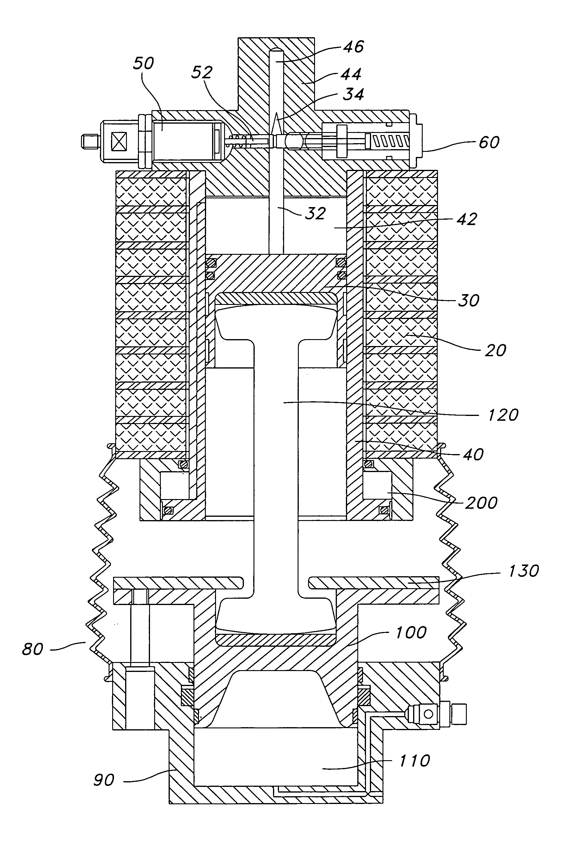
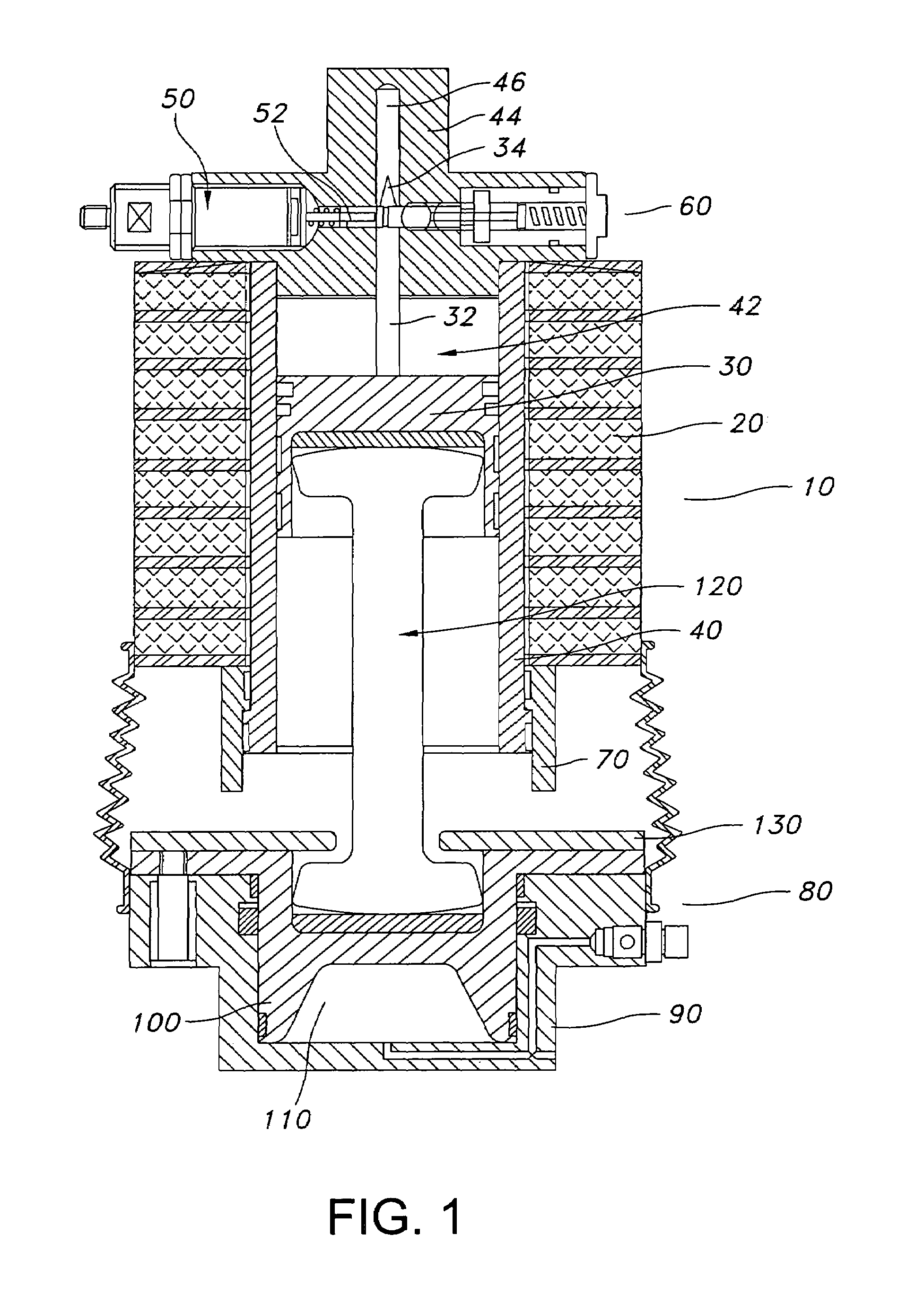
[0048]FIG. 1 shows in longitudinal section a spring element 10 with an auxiliary spring 20 and a hydropneumatic strut (HP strut) to be positioned between the bogie and the body of a rail vehicle. The HP strut has a strut piston 30, which slides longitudinally in cylinder 40. In the pinston space 42 of cylinder 40 there is a hydraulic medium, preferably oil, which via connector 60 is connected with an hydraulic accumulator. Auxiliary spring 20 encloses the HP-strut cylinder 40.

[0049]Cylinder head 44 holds a height sensor 50, the mechanical feedback loop (displacement indicator) 52 of which is designed to move horizontally. Cylinder head 44 also has vertical bore 46, which holds mobile lug 32 connected with piston 30. Lug 32 has conical area 34.

[0050]Cylinder 40 has at its lower end ring 70, which can be moved against a friction resistance relative to cylinder 40 to an end stop that hold ring 70 in the lowest position. Auxiliary spring 20 presses ring 70 against the cylinder 40 end st...


PUM


Abstract

A spring element with a hydropneumatic strut are positioned between the bogie and the body of a rail car, with the strut having a sliding piston in a cylinder, whereby the piston or the cylinder can be connected with the bogie and the other component can be connected with the body, and the piston area of the cylinder is connected with a hydraulic accumulator. A strut that is easy to service and maintain and does not accumulate any appreciable amount of dirt is created by virtue of the fact that the hydropneumatic strut has a hydraulic height regulator valve or a height sensor connected or connectable with a feedback loop, whereby the position of the piston in the cylinder can be adjusted or determined.

Description

BACKGROUND OF THE INVENTION[0001]The within invention concerns a spring element with a hydropneumatic strut to be positioned between the bogie and the body of a rail car, with the strut enclosing a piston that can slide in a cylinder so that the piston or the cylinder can be connected with the bogie and the other component can be connected with the body, and the piston space of the cylinder is connected with a hydraulic accumulator. A spring element of this type is known from, for example, WO 94 / 22702.[0002]Spring elements of this type serving generally as secondary spring elements are known in a wide variety of embodiments. It is known how to adjust the strut height and hence the vehicle height, with height sensors being positioned between the car body and the bogie, by use of the sensors, the desired vehicle height is adjusted via a feedback loop. Sensors of this type become dirty, on the one hand, and on the other hand are positioned in such a way that changing them requires the ...

Claims


Application Information

Patent Timeline
IPC IPC(8): B60G11/58B60G17/027B60G17/04B60G17/056B61F5/02
CPCB60G17/01933B60G17/0272B60G17/04B60G17/056B61F5/02B60G2202/154B60G2202/32B60G2204/112B60G2300/10B60G2500/206B60G2800/012B60G2800/9122
Inventor GAILE, ANTON
Owner LIEBHERR AEROSPACE LINDENBERG
Why Eureka
Try Eureka