Butt coupling structure and method of photonic quantum ring hole emitter

a technology of photonic quantum ring and butt coupling, which is applied in the direction of instruments, optical elements, optical waveguide light guides, etc., can solve the problems of high cost of assembly of specific apparatuses or the like, and achieve the effect of increasing the optical coupling strength of the pqr hole emitter

Inactive Publication Date: 2009-04-21
POSTECH ACAD IND FOUND
View PDF10 Cites 1 Cited by
  • Summary
  • Abstract
  • Description
  • Claims
  • Application Information

AI Technical Summary

Benefits of technology

[0005]It is, therefore, an object of the present invention to provide a butt coupling structure and method of an optical device, e.g., a PQR hole emitter capable of increasing an optical coupling strength of the PQR hole emitter with an optical fiber.

Problems solved by technology

However, in the optical coupling method using micro-lenses, an optical axis alignment between the micro-lenses and the optical fibers needs to be performed within a submicron level and, further, a high cost is required for a specific apparatus or the like to assembly them.

Method used


Image

  • Butt coupling structure and method of photonic quantum ring hole emitter
  • Butt coupling structure and method of photonic quantum ring hole emitter
  • Butt coupling structure and method of photonic quantum ring hole emitter

Examples


Embodiment Construction

[0019]The preferred embodiment of the butt coupling method of the PQR hole emitter in accordance with the present invention will be described with reference to the accompanying drawings.

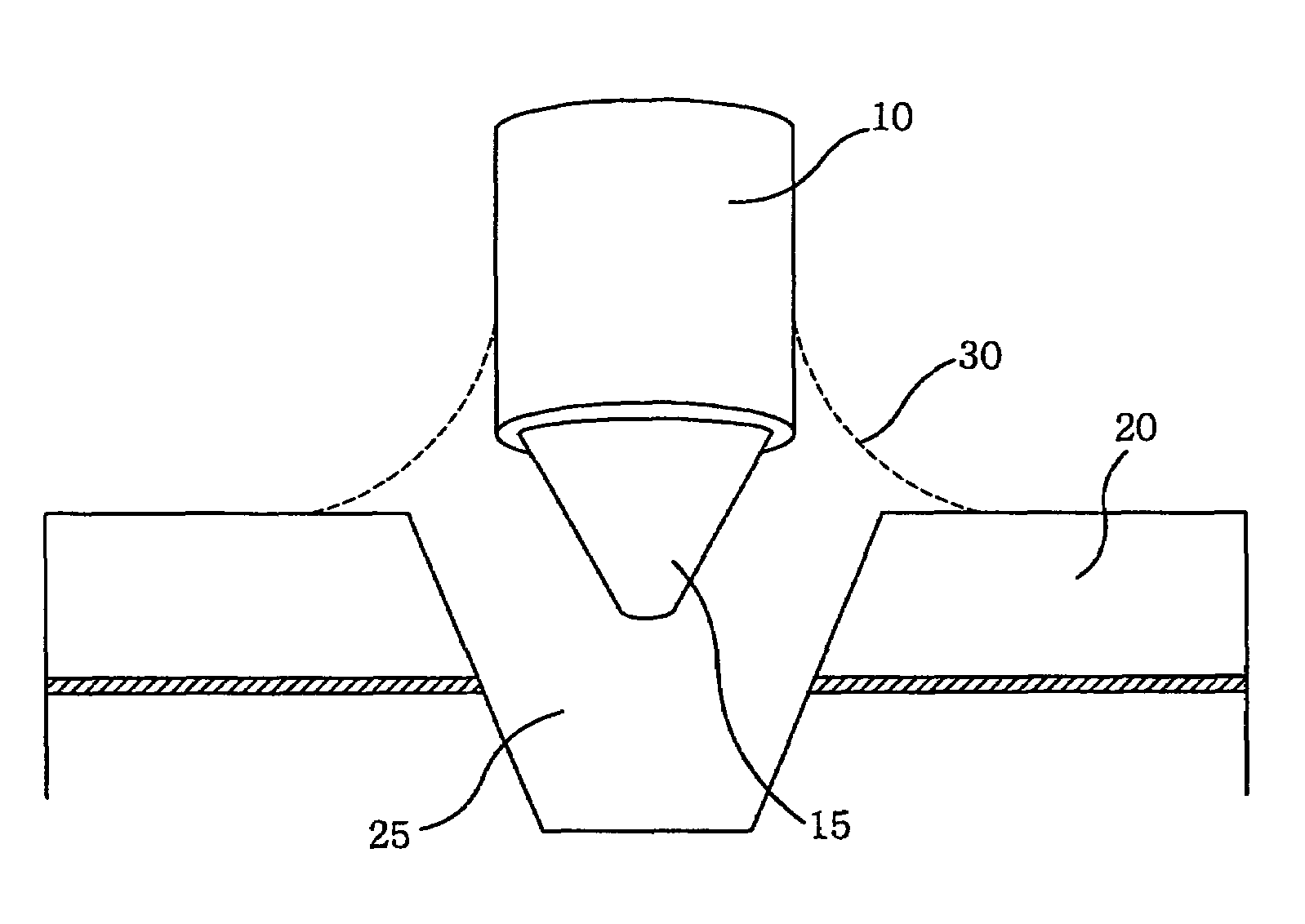
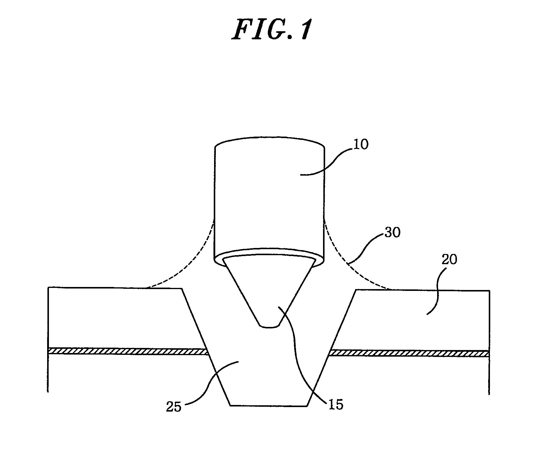
[0020]Referring to FIG. 1, there is shown a butt coupling structure of a PQR hole emitter with an optical fiber constructed in accordance with the present invention.

[0021]An optical fiber 10 includes a multimode optical fiber, and one side thereof has a sharpen end 15. The sharpen end 15 is inserted into a PQR hole 25 formed at a periphery of a PQR hole emitter 20.

[0022]The PQR hole emitter 20 is one of PQR lasers, especially a convex-whispering gallery mode laser in which light is emitted from a convex boundary surface.

[0023]Further, a variable index-matching adhesive 30 is injected into the PQR hole 25 with the sharpen end 15, thereby coupling the optical fiber 10 and the PQR hole emitter 20. The variable index-matching adhesive includes a photo-resist or a photo-resist diluted solution, for exampl...


PUM


Abstract

An optical coupling structure includes a PQR hole emitter having a PQR hole, and an optical fiber whose one side is tapered into the PQR hole. An index-matching solution such as a photo-resist or a photo-resist diluted solution is injected into the PQR hole to adhere the optical fiber and the PQR hole.

Description

[0001]This application is a Continuation-In-Part Application of PCT International Application No. PCT / KR2006 / 001001 filed on Mar. 20, 2006, which designated the United States.TECHNICAL FIELD[0002]The present invention relates to an optical coupling of a light-emitting device; and, more particularly, to a butt coupling structure and a butt coupling method of a PQR (Photonic Quantum Ring) hole emitter using an optical fiber.BACKGROUND ART[0003]As well known in the art, a very high-data rate backbone network for optical communication employs an active component, e.g., a high-quality laser diode (LD) / photo diode (PD), an optical switch, a high-speed router, a DWDM (Dense Wavelength Division Multiplexing) device, a cross connect device or the like. Meanwhile, it is important for a subscriber network in great demand to employ efficient, simply manufacturable, solid and low-priced components. Especially, an efficient optical coupling of an optical device, e.g., a laser, is indispensable fo...

Claims


Application Information

Patent Timeline
Patent Type & Authority Patents(United States)
IPC IPC(8): G02B6/36G02B6/12G02B6/42H01S3/083
CPCG02B6/4202G02B6/4212H01S3/067H01S5/10
Inventor KWON, O'DAELEE, SEUNGEUN
Owner POSTECH ACAD IND FOUND
Why Eureka
Try Eureka