
Charging system for recharging a battery of powered lift ambulance cot with an electrical system of an emergency vehicle

a charging system and ambulance cot technology, applied in the field of ambulance cots, can solve the problems of increasing the risk of back injury or exacerbating an existing one for attendants, and exacerbated problems, so as to reduce work related injuries, reduce the amount of lost work time, and improve the effect of therapeutic cos

Active Publication Date: 2009-04-21
FERNO WASHINGTON
View PDF55 Cites 30 Cited by
  • Summary
  • Abstract
  • Description
  • Claims
  • Application Information

AI Technical Summary

Benefits of technology

The present invention provides a hydraulic lift system for an ambulance cot to assist in lifting and lowering the cot and patient. This system reduces physical strain on emergency medical services and related personnel, reducing the risk of injury and lost work time. The system uses an x-frame design with two hydraulic lift cylinders for raising and lowering the patient, allowing for easier loading of the cot into a vehicle. The system also has an infinite height adjustment range to meet the needs of the attendant. Additionally, a charging system is provided for recharging the battery of an emergency vehicle. These technical effects provide a safer and more efficient means of lifting and lowering patients during emergency medical services.

Problems solved by technology

Unfortunately, lifting or raising a loaded ambulance cot from this low height increases the risk to these attendants obtaining a back injury or exacerbating an existing one.
This problem is exacerbated when handling and transporting a bariatric patient.

Method used


Image

  • Charging system for recharging a battery of powered lift ambulance cot with an electrical system of an emergency vehicle
  • Charging system for recharging a battery of powered lift ambulance cot with an electrical system of an emergency vehicle
  • Charging system for recharging a battery of powered lift ambulance cot with an electrical system of an emergency vehicle

Examples


Embodiment Construction

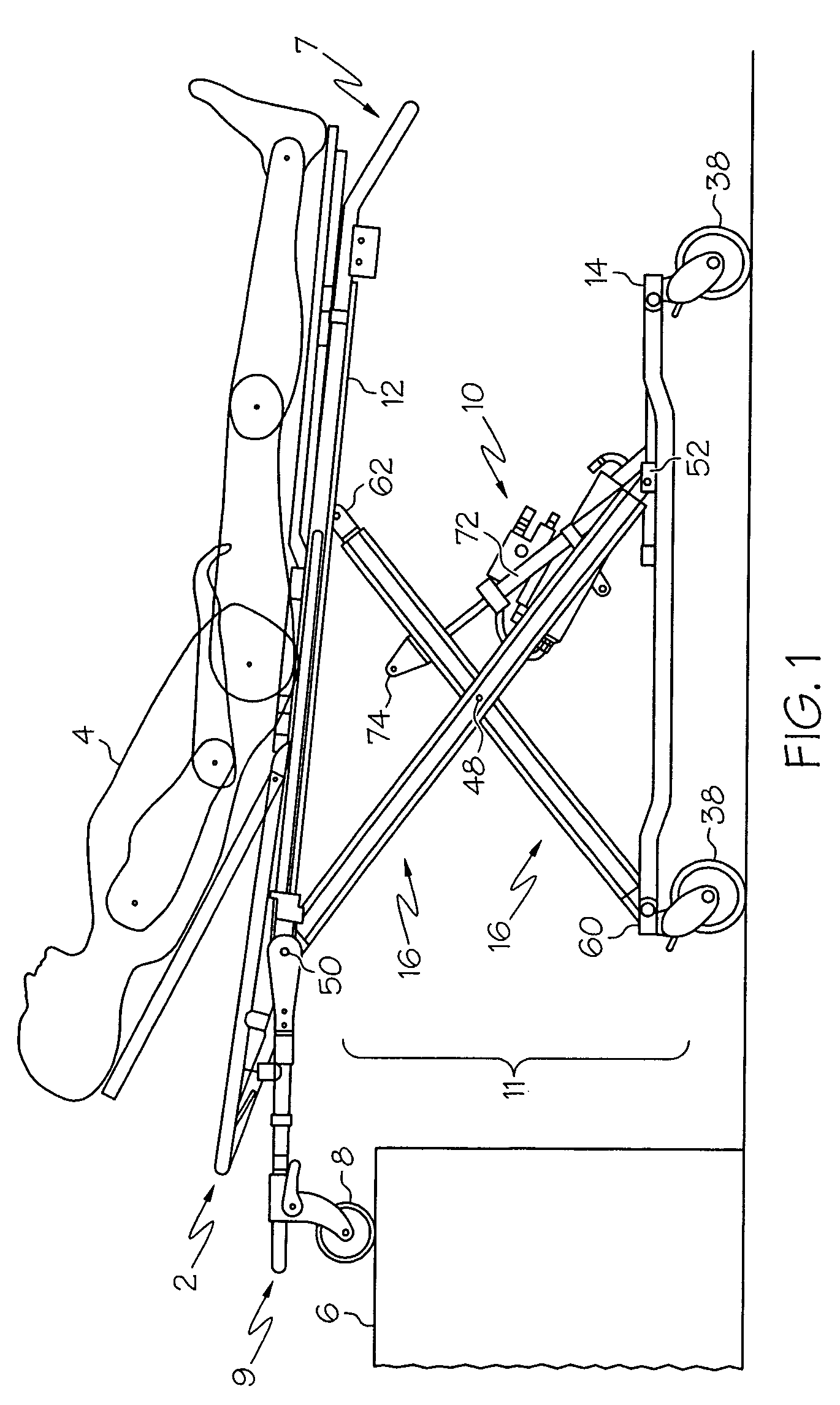
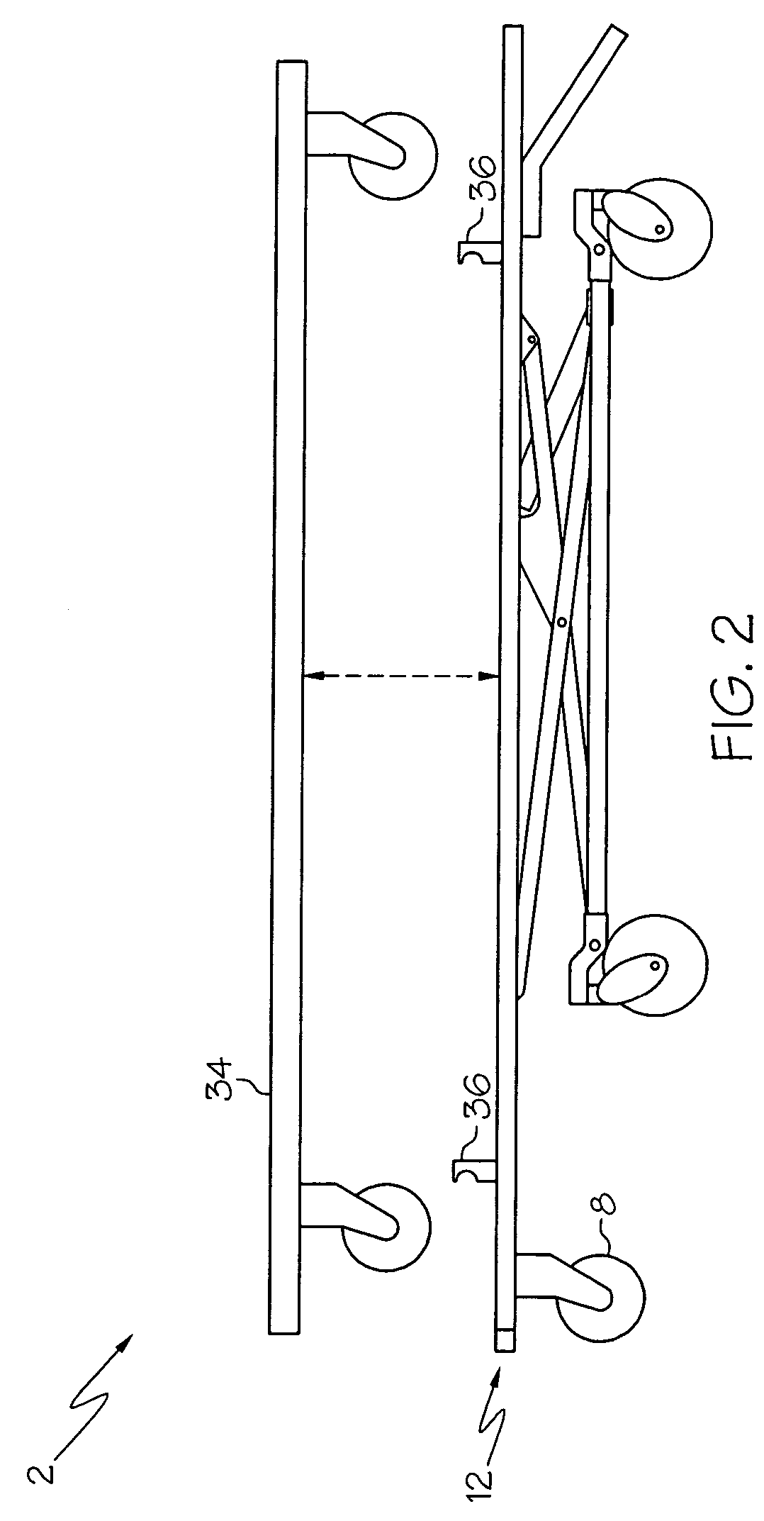
[0023]With reference to FIGS. 1-5, a retractable ambulance cot according to one embodiment of this invention is shown generally as 2. Upon the cot 2 a patient 4 may be supported, and conveniently loaded onto an elevated surface 6, such as for example, the transport bay of an ambulance. It is to be appreciated that the cot 2 functions at ambulance load heights up to about 0.9 meters (about 34 inches), thereby reducing the physical strain of loading an ambulance cot into an ambulance. Additionally, it is to be appreciated that the cot 2 unloaded weighs less than about 61 kilograms (about 135 pounds). The overall dimensions of the cot 2 is about 2.1 meters (about 83 inches) long by about 0.6 meters (about 24 inches) wide by about 0.33 meters (about 13 inches) high in the fully lowered position, a position illustrated by FIG. 2.

[0024]Referring to FIG. 1, the cot 2 is illustrated in a fully elevated position. It is to be appreciated that a single attendant can hold and manipulate the tra...


PUM

PropertyMeasurementUnit
heightaaaaaaaaaa
heightaaaaaaaaaa
heightaaaaaaaaaa

Abstract

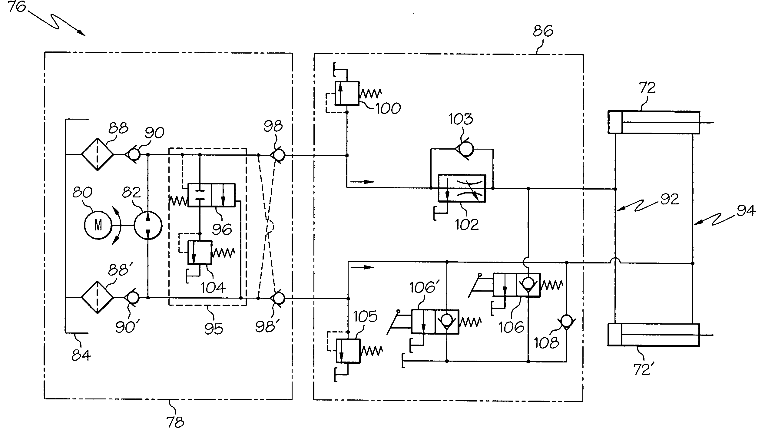
A collapsible hydraulically operated ambulance cot having a support frame, a wheeled base, a support mechanism disposed therebetween, and a lift system for hydraulically moving the upper frame relative to the lower frame is disclosed. The lift system permits a single attendant to raise the cot from a lowered position to a raised position, and an infinite number of positions therebetween, and to raise the wheeled base relative to the support frame to situate the cot onto an elevated surface such as the transport deck of an ambulance. A manual override is also provided to conserve battery power and as a back-up in no-power situations. It is to be appreciated that the above described manual override mode may be used when raising or lowering the cot without power assist, dropping the undercarriage when unloading from a vehicle, and lifting the undercarriage when loading into a vehicle. A charging system for recharging a battery of an electro-hydraulically powered lift ambulance cot with an electrical system of an emergency vehicle is also disclosed.

Description

CROSS-REFERENCE OF RELATED APPLICATIONS[0001]This application is a continuation-in-part of PCT application U.S. Ser. No. 05 / 019,547, filed Jun. 3, 2005, which claims benefit from U.S. provisional application No. 60 / 579,395 filed Jun. 14, 2004 (now abandoned)), all of which are incorporated herein by reference in their entirety.FIELD OF THE INVENTION[0002]This invention relates to ambulance cots and more particularly to an ambulance cot having an electro-hydraulically, operated collapsible frame structure to facilitate loading of the ambulance cot from the ground and into an ambulance by a single operator, and to a charging system for recharging a battery of an electro-hydraulically powered lift ambulance cot with an electrical system of an emergency vehicle.BACKGROUND OF THE INVENTION[0003]In order to situate a conventional non-powered ambulance cot into the back of an ambulance, two or more attendants often must lift the cot from a relatively low height of approximately 15 cm (abou...

Claims


Application Information

Patent Timeline
Patent Type & Authority Patents(United States)
IPC IPC(8): H01M10/46
CPCA61G1/0293A61G1/04A61G1/052A61G1/0567A61G1/0212H01R43/26H02J7/0045H02J7/0054A61G1/0237A61G1/0262H01R13/707H01R13/2421H01R13/447H01R2201/12H02J7/342A61G1/06
Inventor CHOY, EARLSUTTON, SR., W. DALECHINN, ROBERT
Owner FERNO WASHINGTON
Learn More