Optical communication system

a communication system and optical communication technology, applied in multiplex communication, wavelength-division multiplex systems, instruments, etc., can solve the problems of communication disconnection, pause of the overall network, and all other connected communication nodes are affected, so as to achieve high reliability and flexibility in connecting communication nodes.

Inactive Publication Date: 2009-04-21
NIPPON TELEGRAPH & TELEPHONE CORP
View PDF16 Cites 17 Cited by
  • Summary
  • Abstract
  • Description
  • Claims
  • Application Information

AI Technical Summary

Benefits of technology

[0040]According to the optical communication systems of the above-described tenth through twenty-third aspects, it is possible to highly reliably and flexibly connect communication nodes conne

Problems solved by technology

However, in the abovementioned scheme, the problem is such that, in the case where any fault such as disconnection of an optical fiber or failure of a communication node occurs, all the other connected communication nodes are affected.
When they attempt automatic diagnosis, all the other communication nodes connected to the network are affected, and communication disconnection occurs.
Furthermore, another problem is such that, in the case where a communication node is to be added to the same ring, the overall network must be paused.
However, not only is there a problem i

Method used


Image

  • Optical communication system
  • Optical communication system
  • Optical communication system

Examples


embodiment 1

[0096]First to fourth embodiments described hereunder, are described using as an example “8” as N, being the number of input ports and output ports of an N×N arrayed waveguide grating optical multiplexer / demultiplexer (hereunder, N×N-AWG) which functions as a wavelength path establishment circuit, and as n, being the number of communication nodes. However, the invention is not limited to this and it may be such that N is any integer of 2 or more and that n is any integer of 2 or more and less than or equal to N.

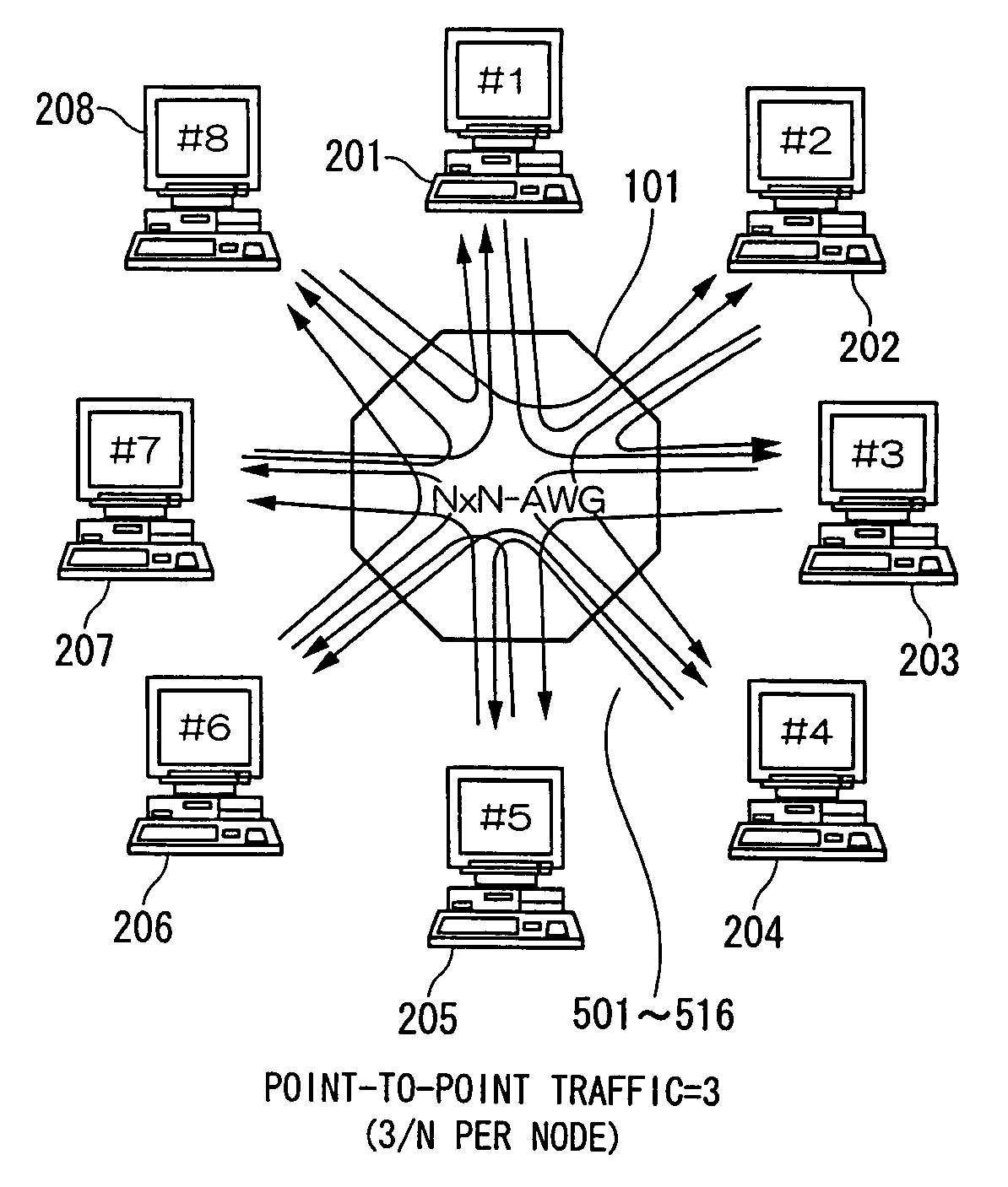
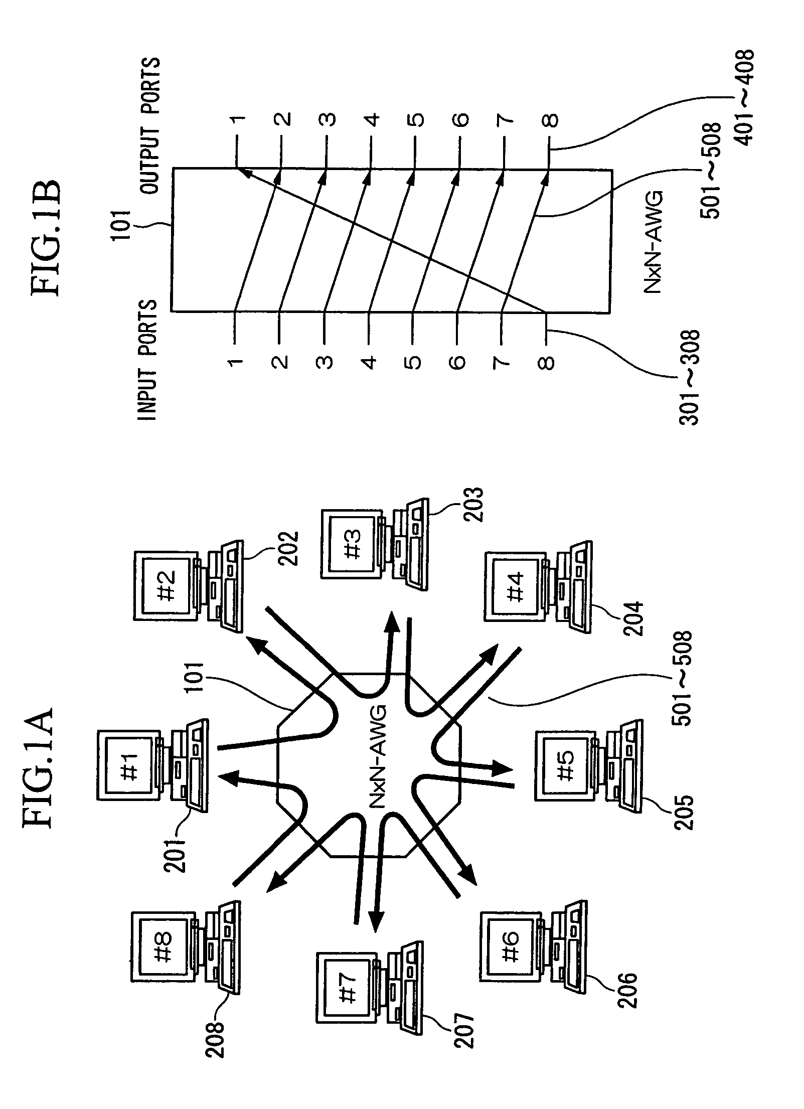
[0097]FIG. 1A and FIG. 1B show a first embodiment of an optical communication system of the present invention. FIG. 1A shows the overall configuration, while FIG. 1B shows an example of transmission paths between input ports and output ports in the N×N-AWG.

[0098]In FIG. 1A, reference symbol 101 is an N×N (here, 8×8)-AWG having 8 input ports 301 to 308 and 8 output ports of 401 to 408, the arrangement being such that; light input to one input port, is output from different res...

embodiment 2

[0106]FIG. 3A and FIG. 3B show a second embodiment of an optical communication system of the present invention. FIG. 3A shows a case with one route (same as the case of the first embodiment) and FIG. 3B shows a case with three routes.

[0107]That is to say, as shown in FIG. 3B, it becomes possible to treble the overall path by forming a new transmission path having a route of #1→#3→#5→#7→#1 and a route of #2→#4→#6→#8→#2, in addition to the transmission path having a route of #1→#2→#3→#4→#5→#6→#7→#8→#1.

[0108]FIG. 4A and FIG. 4B show an example of transmission paths between the input ports and the output ports in N×N-AWG 101 of the second embodiment, FIG. 4A showing an example corresponding to FIG. 3A and FIG. 4B showing an example corresponding to FIG. 3B.

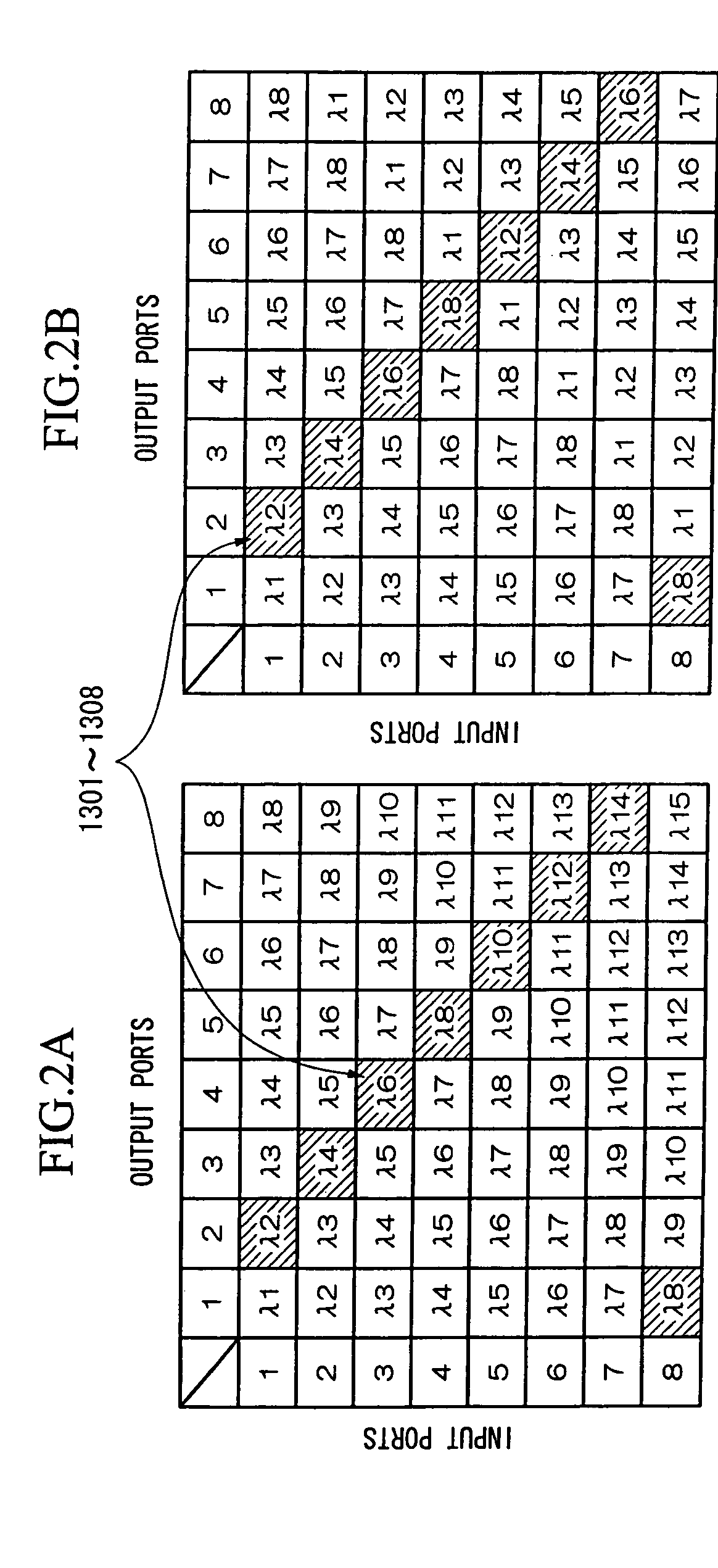
[0109]FIG. 5A and FIG. 5B show an example of setting of wavelengths 1301 to 1316 of optical data signals of the respective communication nodes 201 to 208 in the second embodiment shown in FIG. 3B. FIG. 5A shows a case where the used w...

embodiment 3

[0110]Next is a description of a scheme for fault avoidance in the present optical communication system.

[0111]As above-described, in an optical communication system where an optical data signal is transmitted in only one direction, in the case where a fault occurs in a specific node, it becomes aware of the fact that a fault has occurred somewhere on the present optical network when an optical data signal does not return to the communication node which transmitted the optical data signal. However, in this case, since the part where the fault has occurred cannot be determined, then normally there are many cases where some optical control signals for link query between communication nodes are needed.

[0112]FIG. 6A and FIG. 6B show a third embodiment of an optical communication system of the present invention. FIG. 6A shows an overall configuration, while FIG. 6B shows an example of a transmission path between input ports and output ports in an N×N-AWG.

[0113]Here, regarding the communic...


PUM


Abstract

An optical communication system is constructed which enables highly reliable and flexible connection to communication nodes connected to a path establishment circuit, by utilizing wavelength-routing characteristics of a path establishment circuit such as an arrayed waveguide grating. The optical communication system has multiple communication nodes having a signal output port and signal input port pair, and a path establishment circuit having multiple optical input ports and multiple optical output ports which are set so that optical signals input from the respective optical input ports are output to predetermined optical output ports corresponding to the wavelengths of the optical signals.

Description

BACKGROUND OF THE INVENTION[0001]1. Field of the Invention[0002]The present invention relates to an optical communication system for connecting communication nodes. Specifically, the present invention relates to an optical communication system (optical network system) for flexibly connecting multiple communication nodes at low cost and with high reliability by utilizing the wavelength-routing characteristics of an arrayed waveguide grating, and for sharing memories loaded in respective communication nodes at low cost. More specifically, the present invention relates to an optical communication system which enables flexible connection of communication nodes with high reliability, by utilizing the wavelength-routing characteristics used in an arrayed waveguide grating or the like.[0003]Priority is claimed on Japanese Patent Application No. 2002-338242 filed on Nov. 21, 2002 and Japanese Patent Application No. 2003-326317 filed on Sep. 18, 2003, the contents of which are incorporated h...

Claims


Application Information

Patent Timeline
IPC IPC(8): H04J14/00H04J14/02H04Q11/00
CPCH04J14/0227H04J14/0282H04J14/0283H04Q11/0062H04J14/0246H04J14/025H04J14/0226H04Q2011/0032
Inventor TANOBE, HIROMASAOKADA, AKIRAMATSUOKA, MORITONOGUCHI, KAZUTOSAKAMOTO, TAKASHIMORIWAKI, OSAMU
Owner NIPPON TELEGRAPH & TELEPHONE CORP
Why Eureka
Try Eureka