Acoustic fluid analyzer

a fluid analyzer and acoustic technology, applied in the direction of instruments, specific gravity measurement, borehole/well accessories, etc., can solve the problems of inability to fully control the speed of the pump, unrepresentative samples having altered fluid properties, and the ability to stop the pumping operation

Active Publication Date: 2009-04-28
BAKER HUGHES HLDG LLC
View PDF44 Cites 23 Cited by
  • Summary
  • Abstract
  • Description
  • Claims
  • Application Information

AI Technical Summary

Benefits of technology

[0052]The present invention described herein, therefore, is well adapted to carry out the objects and attain the ends and advantages mentioned, as well as others inherent therein. While a presently preferred embodiment of the invention has been given for purposes of disclosure, numerous changes exist in the details of procedures for accomplishing the desired results. For example, production of the generated signal 17 is not limited to a signal generator 16 disposed within or adjacent to the sampling system 22, but could include signal generators from remote sources. The remote signal sources could be from ballistics, geophones, airguns, or any other known signal-generating source. These and other similar modifications will readily suggest themselves to those skilled in the art, and are intended to be encompassed within the spirit of the present invention disclosed herein and the scope of the appended claims.

Problems solved by technology

After having these components come out of solution, they typically cannot be easily recombined which results in an unrepresentative sample having altered fluid properties.
However this method has some drawbacks when particulate matter is present in the fluid thereby resulting in possible erroneous results.
Unfortunately the pumping devices currently in use with the above described sampling devices have some inherent drawbacks.
For example, control of the electrical or hydraulic actuation means of the presently used pumping systems is not accurate that in turn results in an inability to fully control the speed of the pumps.
Not being able to fully control pump speed prohibits the capability of ceasing pumping operations should the pressure of the connate fluid fall below its bubble point and also hinders the ability to accurately measure the bubble point.
Since sampling connate fluid at pressures below its bubble point negatively affects the accuracy of the sampling data results.

Method used


Image

  • Acoustic fluid analyzer
  • Acoustic fluid analyzer
  • Acoustic fluid analyzer

Examples


Embodiment Construction

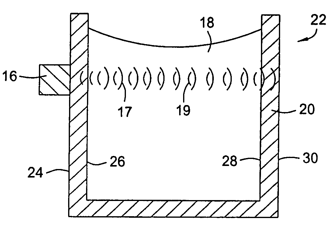
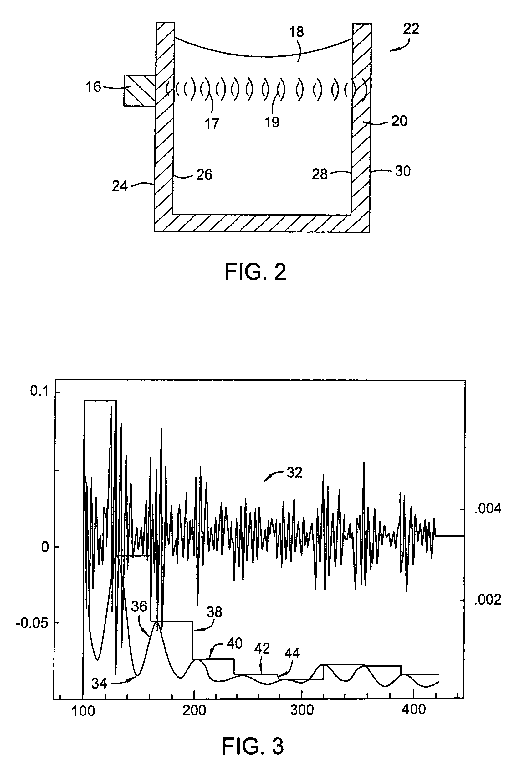
[0022]The method disclosed herein provides a manner of evaluating the compressibility of a fluid based on the measured fluid density and measured sound speed of the fluid. With reference now to FIG. 2, an embodiment of a sampling system 22 of the present device is illustrated in a partial cut-away view. The sampling system 22 of FIG. 2 comprises a vessel or container 20 in cooperation with a signal generator 16. The outer surface of the container 20 can have a radial or rectangular configuration as well as the shape of a tubular. Optionally the vessel or container 20 can be comprised of a conduit or pipe.

[0023]As shown, the container 20 should be capable of retaining and storing the fluid 18 within its confines during analysis. Although shown as open at its top, the container 20 can also be sealed thereby fully encapsulating the fluid 18 therein. The signal generator 16 can be attached to the outer or first wall 24 of the container 20 or maintained in place. As will be described her...


PUM

PropertyMeasurementUnit
resonant frequencyaaaaaaaaaa
sound speedaaaaaaaaaa

Abstract

A method of determining properties of a formation fluid based on measurements of fluid sound speed, a measurement of fluid density, or both. The properties include compressibility, thermal conductivity, and gas oil ratio. The compressibility of a fluid is equal to the reciprocal of the product of the sound speed squared and fluid density. The density and the sound speed can be measured acoustically. The method further includes a manner of processing data including applying the Savitzky-Golay method and utilizing a variable thresholding technique.

Description

BACKGROUND OF THE INVENTION[0001]1. Field of the Invention[0002]The invention relates to wellbore evaluation operations. More specifically, the present invention relates to an apparatus and method for ascertaining the compressibility of connate fluid within a wellbore and the presence of a gaseous phase in that fluid.[0003]2. Description of Related Art[0004]The sampling of connate fluid contained in subterranean formations provides a method of testing formation zones of possible interest with regard to hydrocarbon bearing potential. This involves recovering a sample of any formation fluids present for later analysis in a laboratory environment while causing a minimum of damage to the tested formations. The formation sample is essentially a point test of the possible productivity of subsurface earth formations. Additionally, a continuous record of the control and sequence of events during the test is made at the surface. From this record, valuable formation pressure and permeability ...

Claims


Application Information

Patent Timeline
Patent Type & Authority Patents(United States)
IPC IPC(8): G01N29/024G01N29/44G01N29/22
CPCE21B49/10G01N29/024G01N29/032G01N29/222G01N2291/02433G01N2291/02881G01N29/22
Inventor DIFOGGIO, ROCCOYAO, WEIMIN
Owner BAKER HUGHES HLDG LLC
Why Eureka
Try Eureka