Endoscopy system
a technology of endoscopy and endoscope, which is applied in the field of endoscopy system, can solve the problems of large gap between the skill of an inexperienced doctor and that of a richly experienced one, and the time-consuming and laborious of manual insertion
- Summary
- Abstract
- Description
- Claims
- Application Information
AI Technical Summary
Benefits of technology
Problems solved by technology
Method used
Image


Examples
first embodiment
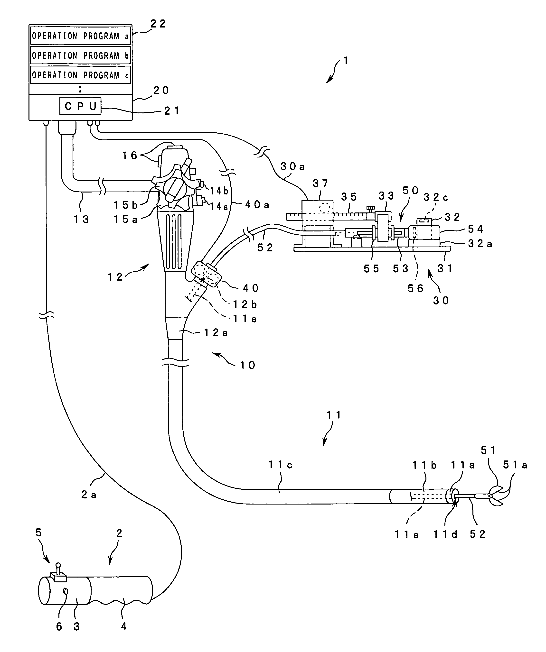
[0043]the present invention will now be described with reference to FIGS. 1 to 12.
[0044]Referring to FIG. 1, an endoscopy system 1 primarily includes an operation instructing device 2, an endoscope 10, a control device 20, serving as a light source and a video processor, a motor-driven accessory operating device (hereinafter, referred to as a motor-driven operating device) 30, serving as an operating device, and a motor-driven forward / backward accessory insertion section moving device (hereinbelow, referred to as a motor-driven forward / backward moving device) 40, serving as a forward / backward moving device. According to the present embodiment, the operation instructing device 2, the control device 20, the motor-driven operating device 30, and the motor-driven forward / backward moving device 40 constitute an endoscopic operation assist apparatus.
[0045]The control device 20 includes a CPU 21, serving as a control unit, and a memory device 22, serving as a memory unit, such as a hard di...
second embodiment
[0136]the present invention will now be described with reference to FIGS. 16 to 17B.
[0137]An endoscopy system 1A shown in FIG. 16 includes an accessory specifying device (hereinafter, referred to as a selector) 9, serving as accessory specifying means. A motor-driven operating device 30A includes a rotary motor 39 for rotating the distal end of the handle 53 of the basket forceps 50C about the long axis of the sheath 52.
[0138]A torque transmission gear (hereinbelow, referred to as a gear) 39b, serving as a spur gear, is attached to a motor shaft 39a of the rotary motor 39. The rotary motor 39 is electrically connected to a control device 20 via an electric cable 39c. The rotary motor 39 is fixed to the rear surface of a base 31a shaped substantially like a hat.
[0139]The base 31a has a hole 31c in which the gear 39b of the rotary motor 39 is exposed. In stead of the mount 38, the base 31a has a rotation holding member (hereinafter, referred to as a holding member) 31b for rotatably h...
PUM
 Abstract
Description
Claims
Application Information