Spindle motor and disk drive unit

a spindle motor and disk drive technology, applied in the direction of instruments, recording information on magnetic disks, and recording on magnetic disks, can solve the problems of insufficient eccentric action, optical head being unable to accurately read information from a disk or accurately write information to a disk, and unable to achieve sufficient eccentric action, etc., to achieve the effect of more reliably reading and greater eccentricity

Inactive Publication Date: 2009-04-28
TOKYO PARTS IND CO LTD
View PDF17 Cites 6 Cited by
  • Summary
  • Abstract
  • Description
  • Claims
  • Application Information

AI Technical Summary

Benefits of technology

[0016]In accordance with an advantageous embodiment of the invention, the rotor side end surface of the sintered oil-impregnated bearing that rotatably supports the rotating shaft of the rotor is covered with a magnetic cap. The opposing face provided on a portion of the magnetic cap is formed in a shape so as to be near the annular magnet provided on the rotor. For this reason, the rotor becomes eccentric due to the attractive force between the opposing face near the annular magnet and the annular magnet, and the magnetic cap covers the end surface of the sintered oil-impregnated bearing, thereby preventing oil from scattering. Further, the stator base has an arc shaped magnetic body attached thereto opposite the drive magnet, attracting the rotor outer periphery so as to cause eccentricity. Thus, because the arc shaped magnetic body is disposed at a position that includes the symmetrical axis direction of the opposing face that passes through the rotation center axis line of the rotor (axis line Z described below), that is, because the opposing face of the magnetic cap and the arc shaped magnetic body are disposed in a prescribed direction moving outwards from the rotating center of the rotor outwards, the causing-to-be-eccentric can be efficiently performed.
[0018]Further, as shown in a further embodiment in accordance with the invention, when the symmetric axis direction of the opposing face substantially matches the symmetric axis direction of the arc shaped magnetic body, the eccentricity action is maximized, achieving better effects. In other words, because the action to make the rotor eccentric is concentrated in one direction, rotation loss caused by an attractive force not contributing to the eccentricity can be suppressed, allowing reliable eccentricity.
[0019]Further, as shown in additional advantageous embodiments, a constitution wherein both opening angles of the opposing face and the arc shaped magnetic body are 180° or less, and a constitution wherein the opening angle of the arc shaped magnetic body is no greater than the opening angle of the opposing face can be suitably employed. With such constitutions, rotation loss caused by an attractive force not contributing to eccentricity can be further efficiently inhibited, allowing reliable eccentricity.
[0022]With such a disk drive unit, when the read head moving direction substantially matches the symmetric axis direction of the opposing face, signals recorded on the disk can be more reliably read.
[0023]According to the present invention, using a simple configuration of an annular magnet and magnetic cap opposite the annular magnet, a rotor can be made eccentric while oil scattering is prevented, and / or a rotor can be put in a state where it is pulled in an axial direction. Further, because an arc shaped magnetic body is provided at a position that includes the symmetric axis direction of the opposing face that passes through rotation center axis line of the rotor (axis line Z described below), and the outside of the rotor is pulled in the rotating shaft direction using this arc shaped magnetic body, greater eccentricity can be achieved.Thus, the present application provides a small spindle motor that improves axial run-out, prevents oil from scattering, and has excellent versatility, and a disk drive unit using the motor.

Problems solved by technology

However, unlike a roller bearing, clearance is required between a metal bearing and rotating shaft, and due to this clearance, axial run-out of the rotating shaft becomes larger than that with a roller bearing.
This axial run-out of the rotating shaft becomes surface run-out of a disk surface or axial run-out of a disk when a disk is mounted on a turntable and rotatably driven, causing such disadvantages as an optical head being unable to accurately read information from a disk or accurately write information to a disk.
As suggested in Laid-open Japanese Patent No. 2004-7905, with a disk drive unit configured such that a rotor is made eccentric using a magnetic generator disposed on the rotor and a magnetic attractor covering a bearing end on the stator side, because an attractive force is exerted near the rotating shaft, obtaining sufficient eccentric action is difficult unless this attractive force is strong.
In such a constitution, a prescribed section of a magnetic plate shaped stator core comprising a plurality of stacked magnetic plates is cut away, thereby creating magnetic unbalance with respect to a drive magnet provided on a rotor, thus causing the rotor to be eccentric in a certain direction.
Further, because assembling a stator core as a drive device requires that the assembling direction be determined, such assembly is extremely troublesome.
Further, because a specialized motor is required for such a disk drive, the use of such motor is also limited.

Method used


Image

  • Spindle motor and disk drive unit
  • Spindle motor and disk drive unit
  • Spindle motor and disk drive unit

Examples


Embodiment Construction

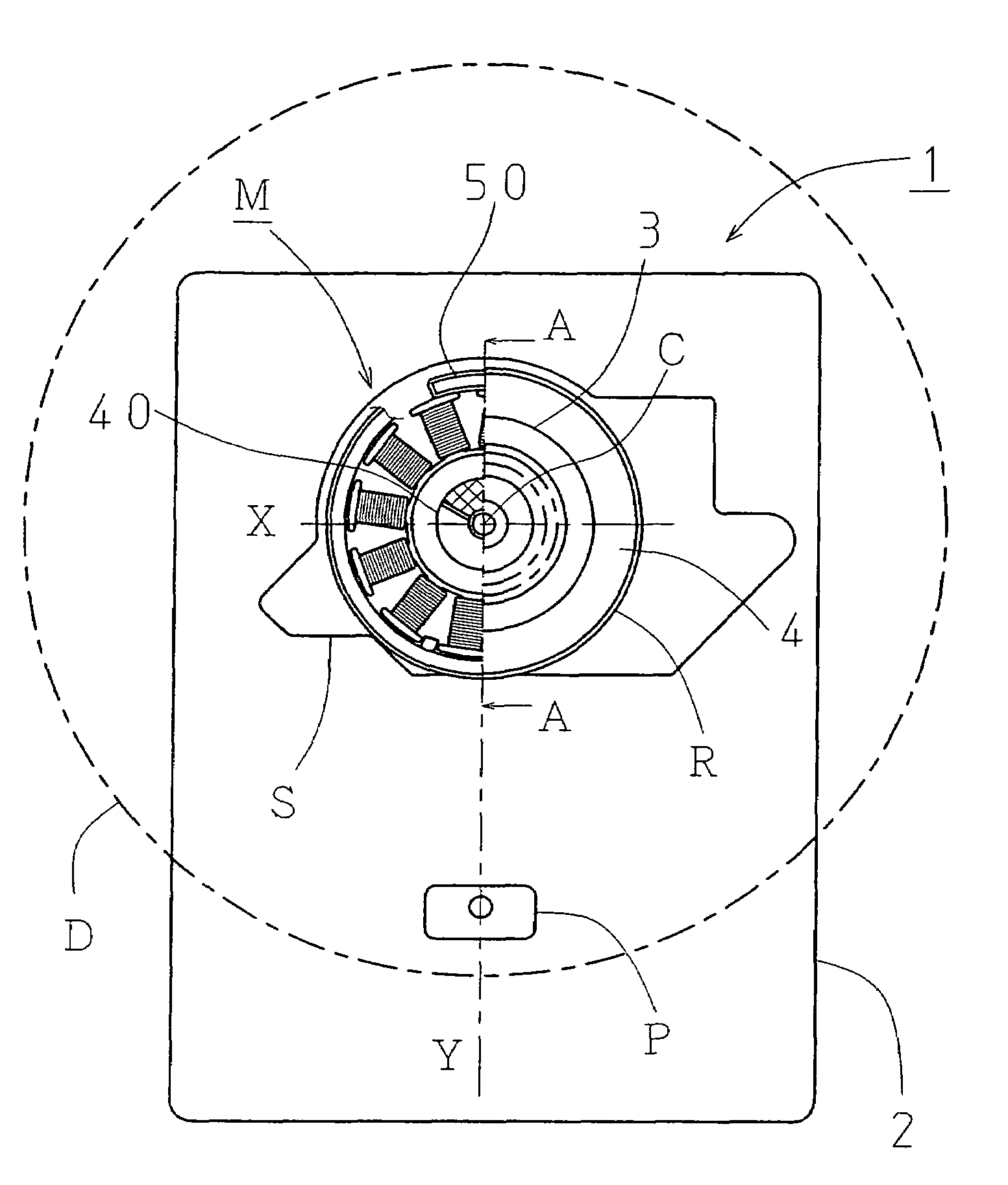
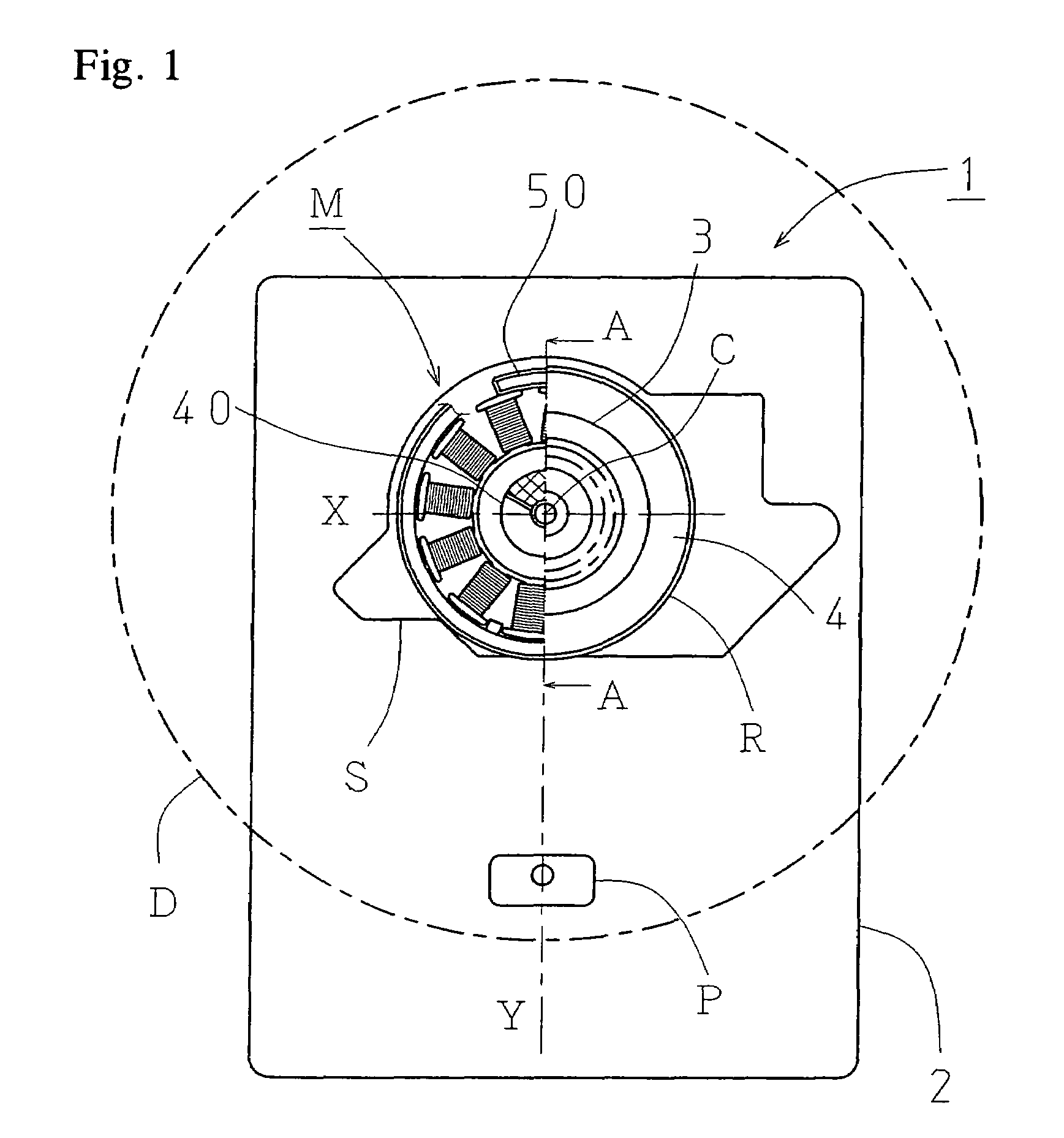
[0029]A disk drive unit according to the present invention will be explained with reference to FIG. 1. FIG. 1 is a plan view showing a disk drive unit, with the upper surface of the rotor cut in half along the line A-A and a portion of the rotor outer periphery cut away.

[0030]A disk drive 1 comprises, on a chassis 2, a spindle motor M and a pickup P that serves as a read head. The pickup P is attached on the chassis 2 so that the optical axis of a laser beam passes through a rotation center C of the spindle motor M and moves along an axis line Y (first axis line) parallel to the rotation plane of a disk D. Explanations of a mechanism to move a pickup, signal processing, a motor drive circuit and the like are omitted, as they do not directly relate to the present invention.

[0031]Here, to simplify the explanation, a line passing through the rotation center C, parallel to the rotation plane of the disk D, and intersecting with the axis line Y at right angles shall be designated axis li...


PUM

PropertyMeasurementUnit
opening angleaaaaaaaaaa
opening anglesaaaaaaaaaa

Abstract

A simple configuration allows a rotor of a spindle motor to be eccentric in the pickup moving direction, and improves axial run-out caused by clearance between a rotating shaft and bearing. An arc shaped magnetic body is disposed on a base of a spindle motor opposite a drive magnet and in the same direction as the opposing face, thereby generating an attractive force on the outer periphery side of the rotor.

Description

BACKGROUND OF THE INVENTION[0001]The present invention relates to a spindle motor for rotatably driving an optical disk, magneto-optical disk or the like, and a disk drive unit comprising the spindle motor and an optical head.[0002]Known disk drive units comprising a head mechanism for reading information recorded in a disk or writing information to a disk include such optical disk and magneto-optical disk drive units as CD, DVD, and MD disk drives.[0003]For such disk drive unit, an outer rotor type brushless motor is employed as a spindle motor for rotatably driving a disk. A rotating shaft of the spindle motor comprises a turntable on which a disk is placed, and is rotatably supported by a stator using a bearing.[0004]A sintered oil-impregnated metal bearing is generally used as the bearing. This is because such a bearing is less expensive than a roller bearing and thus can reduce the costs of a motor and device. However, unlike a roller bearing, clearance is required between a me...

Claims


Application Information

Patent Timeline
Patent Type & Authority Patents(United States)
IPC IPC(8): H02K5/167G11B19/20H02K5/24H02K7/09
CPCH02K7/09H02K5/163H02K7/085H02K29/08
Inventor TSUCHIYA, MASAHISANISHIDATE, MASAHIRO
Owner TOKYO PARTS IND CO LTD
Why Eureka
Try Eureka