Optical demodulating apparatus and method

a demodulating apparatus and optical technology, applied in the field of optical communication, can solve the problems of adding to the complexity and cost of such prior art implementations, two split signals interfering with each other both constructively and destructively, so as to achieve the effect of preventing undesirable thermal sensitivities

Active Publication Date: 2009-04-28
ALCATEL-LUCENT USA INC +1
View PDF8 Cites 37 Cited by
  • Summary
  • Abstract
  • Description
  • Claims
  • Application Information

AI Technical Summary

Benefits of technology

[0006]This innovative demodulator construction—from a single free-space Michelson interferometer—results in a demodulator that is compact, reliable, and may be constructed to be substantially immune from undesirable thermal sensitivities.

Problems solved by technology

As a result, in order to provide such temperature control and stabilization, additional performance monitoring and feedback control components are required which unfortunately, adds to the complexity and cost of such PRIOR ART implementations.
Upon striking Point C, the two split signals interfere with each other both constructively- and destructively.
Upon striking Point D, the two split signals interfere with each other both constructively and destructively.

Method used


Image

  • Optical demodulating apparatus and method
  • Optical demodulating apparatus and method
  • Optical demodulating apparatus and method

Examples


Embodiment Construction

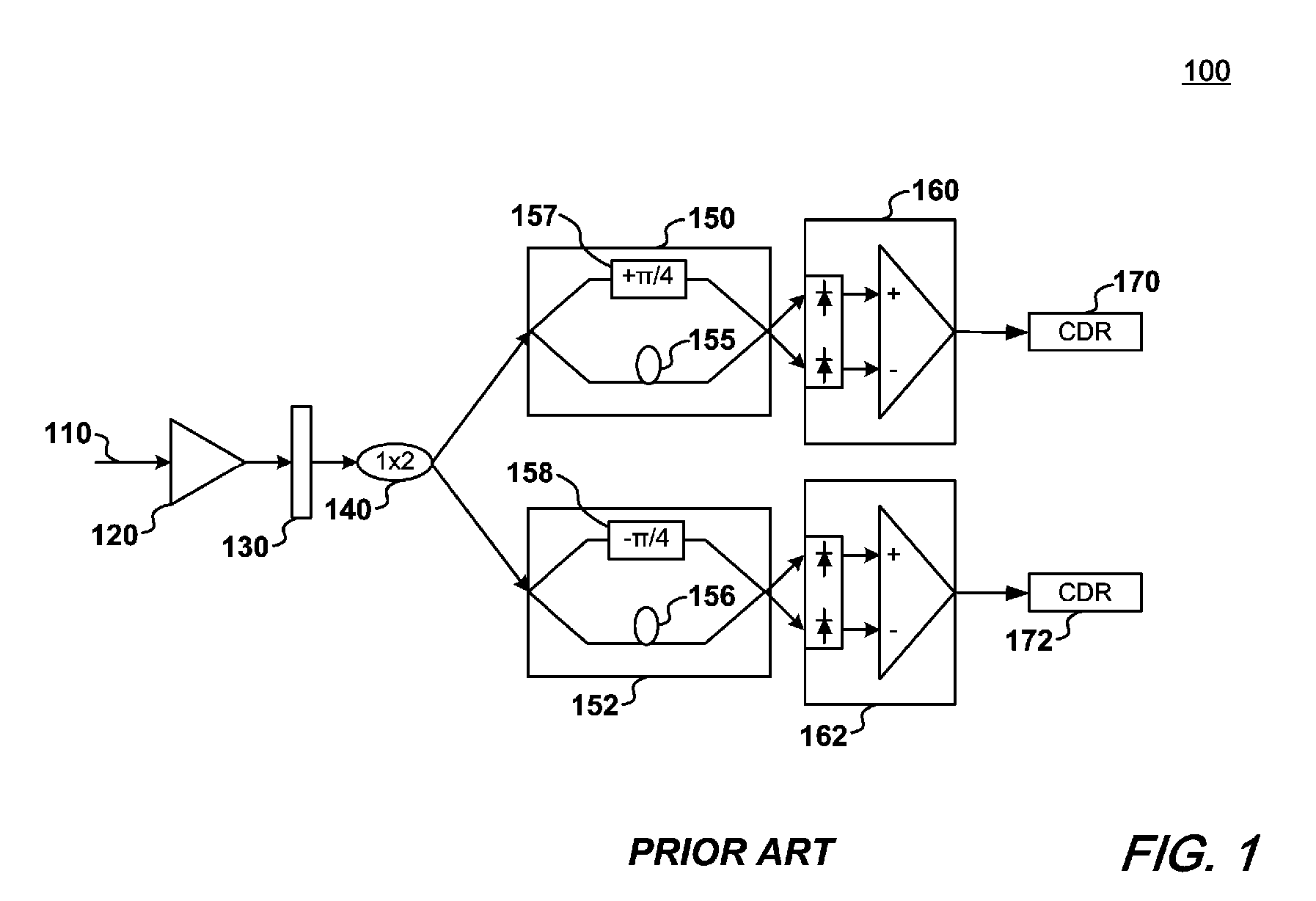
[0011]With initial reference to FIG. 1, there is shown a generalized, PRIOR ART optical DQPSK demodulator 100. With such a PRIOR ART optical demodulator, an optical DQPSK signal 110 having 2 bit / symbol say, is amplified through the effect of an optical amplifier 120, the output of which is subsequently filtered by an optical filter 130 and then split by 1×2 optical coupler / splitter 140.

[0012]Since a DQPSK signal comprises two tributaries, the 1×2 split of the optical coupler 140 is necessary to provide signal(s) to the two optical delay interferometers (ODIs) 150, 152 each including a delay loop 155, 156 and a phase shifter 157, 158, respectively. (Note that the phase shift in this exemplary discussion is shown as +π / 4 and −π / 4). As noted before, these two phase shifts have to be precisely controlled and maintained. More specifically, for 40-Gb / s DQPSK systems, the free spectral range (FSR) of the ODI is approximately 20 GHz. The tolerance to the frequency mismatch resulting from no...


PUM


Abstract

An optical demodulator and accompanying method(s) that demodulates a DQPSK signal employing a single optical delay interferometer comprising a free-space Michelson interferometer having two optical paths, connected to a 1×2 coupler. Positioned within an arm of the Michelson interferometer is a phase shifter that produces a phase difference of π / 2 between the two paths. The resulting demodulator is compact, reliable, and may be constructed to be substantially immune from undesirable thermal sensitivities.

Description

FIELD OF THE INVENTION[0001]The present invention relates generally to the field of optical communications and in particular to methods and apparatus for demodulating and receiving optical signals having Differential-Quadrature-Phase-Shift-Keying (DQPSK) format(s).BACKGROUND OF THE INVENTION[0002]Optical DQPSK is a promising modulation format that is attracting considerable commercial attention as a result of its high receiver sensitivity, high spectral efficiency (SE), high filtering and dispersion tolerance(s). Of particular interest, DQPSK may be used in combination with amplitude modulation to achieve even higher spectral efficiencies.[0003]In optical DQPSK transmission, data is conveyed by an optical phase difference between adjacent bits. In order to detect the data contained within a DQPSK transmission, an optical demodulator is used to convert the phase-coded signal into intensity-coded signals. Typically, such optical demodulators are constructed from a pair of optical dela...

Claims


Application Information

Patent Timeline
Patent Type & Authority Patents(United States)
IPC IPC(8): H04B10/04H04B10/12
CPCH04B10/66
Inventor LIU, XIANG
Owner ALCATEL-LUCENT USA INC
Why Eureka
Try Eureka