Method and apparatus for gas purification

a technology of gas purification and gas filter, which is applied in the direction of separation process, colloidal chemistry, dispersed particle separation, etc., can solve the problems of greater than 50 ppb of nsub>2/sub>o, potential hazard of acetylene and other hydrocarbons in air, explosion hazards, etc., and achieve the effect of superior n2o removal efficiency

Inactive Publication Date: 2009-05-05
PRAXAIR TECH INC
View PDF18 Cites 74 Cited by
  • Summary
  • Abstract
  • Description
  • Claims
  • Application Information

AI Technical Summary

Benefits of technology

[0032]The process and apparatus of the present invention provide surprisingly superior N2O removal efficiency over prior art processes and systems.

Problems solved by technology

Acetylene and other hydrocarbons in air present a potential hazard.
The high boiling hydrocarbons can accumulate in the liquid oxygen and create an explosion hazard.
The presence of greater than 50 ppb of N2O can be a serious problem for cryogenic air separation units (ASU) because it can form solid deposits in distillation columns.
This can result in degraded performance and can even cause blockage of heat exchangers.
However, given the similar electronic structure of N2O and CO2, and the nearly 1000-fold difference in gas phase concentration between N2O and CO2 in air, this methodology is difficult to apply.

Method used


Image

  • Method and apparatus for gas purification
  • Method and apparatus for gas purification
  • Method and apparatus for gas purification

Examples


example 1

N2 Coadsorption Effects

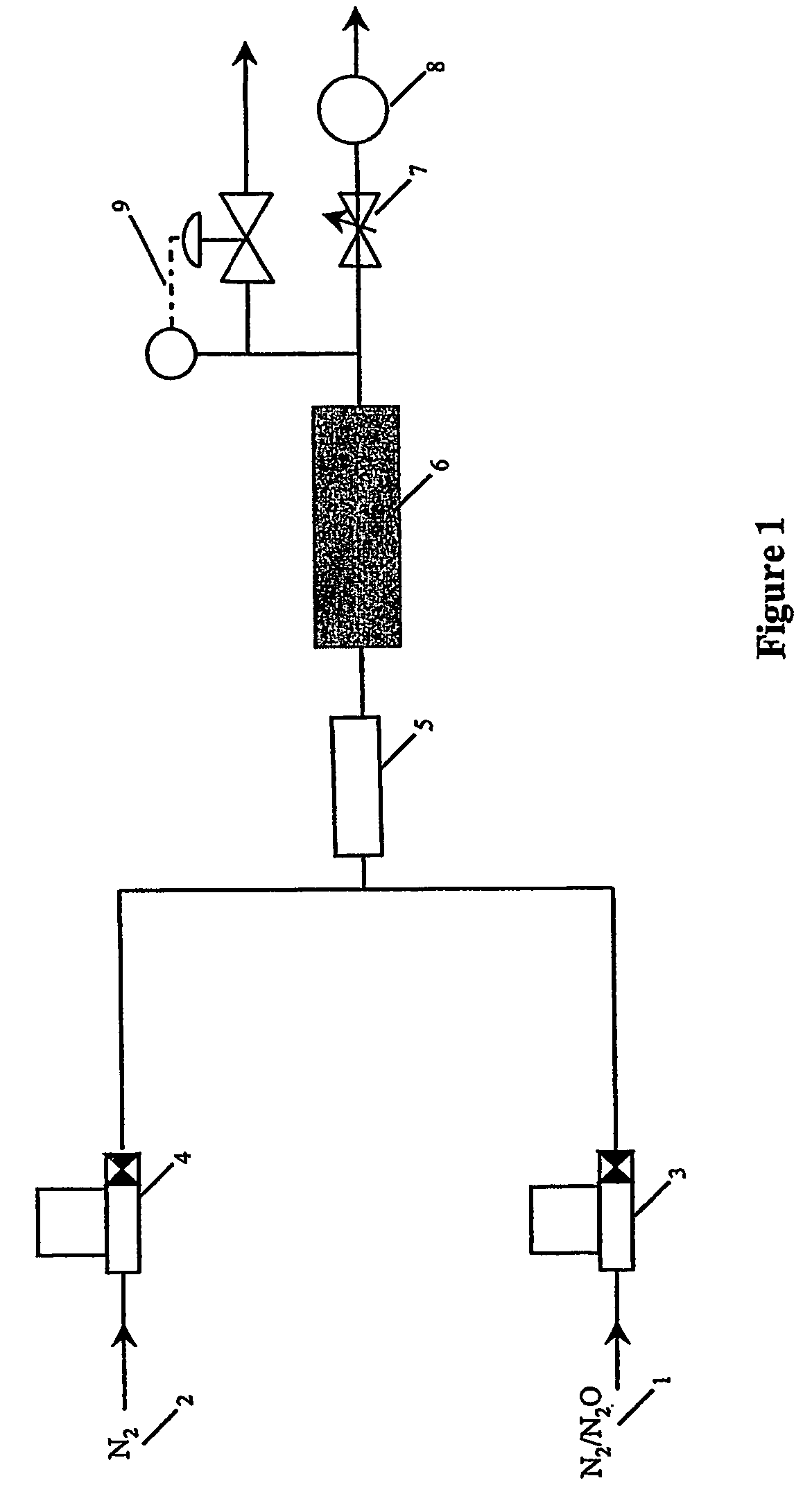
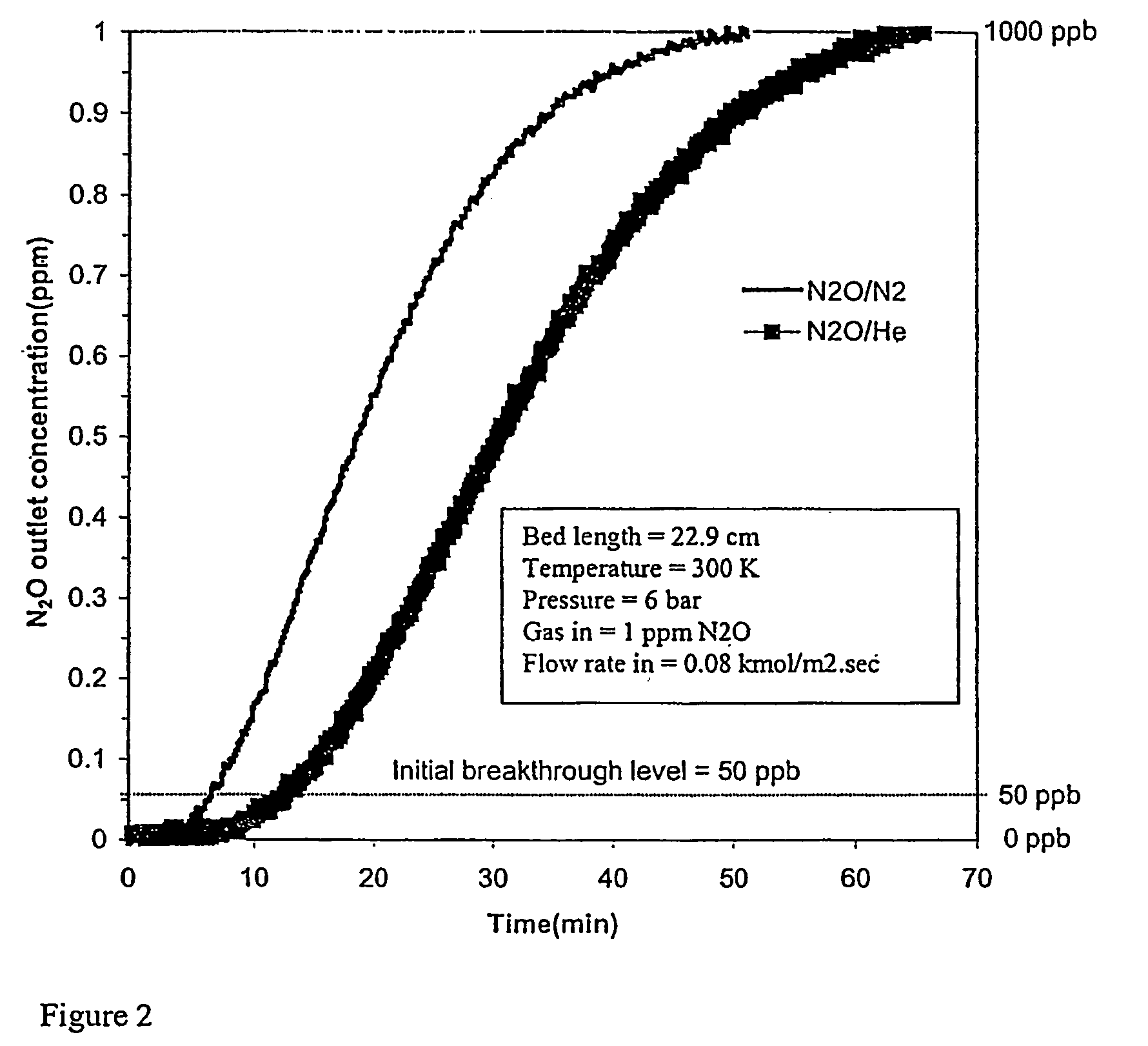
[0067]Adsorbents were tested as described above to determine the effect of N2 coadsorption upon the adsorption of N2O. The results of the saturation capacity of N2O (1.0 ppm) in N2 and in He on various adsorbents are compared in Table 1 below. These results were determined for feed conditions of 6.0 bar, 300° K. and 0.08 kmol / m2 s molar flux using a 22.9 cm or 5.6 cm adsorbent bed length. The SiO2 / Al2O3 ratio is specified for some adsorbents in the table, e.g. NaX (SiO2 / Al2O3=2.3). FIG. 2 shows N2O breakthrough curves for adsorbent 13X (NaX 2.5) for N2O in N2 and N2O in He.

[0068]

TABLE 1Effect of N2 Coadsorption Upon N2O LoadingN2O loadingN2O loading(mmol / gm)(mmol / gm)1.0 ppm1.0 ppmPreferredMaterialN2O / HeN2O / N2AdsorbentsNaY4.06 × 10−41.42 × 10⁻⁴NaZSM5 1.7 × 10−33.59 × 10−4NaKX4.58 × 10−413X NaX (2.5)9.55 × 10−46.09 × 10−4NaX (2.3)1.73 × 10−37.03 × 10−4CaX1.98 × 10−3Na-Mordenite6.38 × 10−3Clinoptilolite (CS400)8.86 × 10−23.60 × 10−3XLiX (2.3) 5.5 × 10−31.22 × 10−...

example 2

N2 Isotherms

[0070]Isotherms for N2 at 300° K were determined for various adsorbents over a range of pressures which included typical feed pressures to a prepurifier of a cryogenic air separation unit. Example isotherms are shown in FIG. 3. The pure component N2 loadings from these isotherms are compared in Table 2 for various adsorbents at 6.0 bar.

[0071]

TABLE 2Equilibrium Loadings of N2 at 6.0 bar, 300° KMaterialN2 loading (mmol / gm)Silicalite0.68H-ZSM50.744A1.11NaY0.85NaZSM5NaKX0.8613X NaX (2.5)1.30NaX (2.3)1.33CaX1.53Na-Mordenite1.40Clinoptilolite (CS400)0.64LiX (2.3)1.71LiX (2.0)2.29Chabazite1.22Clinoptilolite (TSM140)1.23

example 3

Breakthrough at 50 ppb N2O

[0072]The average N2O loading (IBL) of the adsorbent bed was determined at 50.0 ppb N2O from the same N2O / N2 tests reported in Table 1 above. Typical breakthrough results are illustrated in FIG. 4. The IBL values (reflecting not only the 50 ppb breakthrough, but also N2 coadsorption) are compared for various adsorbents in Table 3 and shown in FIG. 5. Separation factors were also computed using Equation 3. The N2 loadings at 6 bar from Table 2 are used in Equation 3 to represent the working capacity of N2 in the process.

[0073]N2O working capacities can be computed either from the saturation loadings of N2O / N2 or from the average loadings of N2O at the IBL. The separation factor computed from the average loadings at the IBL is the preferred method since it reflects both the equilibrium and dynamic effects of the adsorbent. Nevertheless, the former method (which reflects equilibrium effects only) is acceptable when only isotherms and no breakthrough data are a...


PUM

PropertyMeasurementUnit
pressureaaaaaaaaaa
pressureaaaaaaaaaa
temperatureaaaaaaaaaa

Abstract

This invention comprises an adsorption process for the removal of at least N2O from a feed gas stream that also contains nitrogen and possibly CO2 and water. In the process the feed stream is passed over adsorbents to remove impurities such as CO2 and water, then over an additional adsorbent having a high N2O / N2 separation factor. In a preferred mode the invention is an air prepurification process for the removal of impurities from air prior to cryogenic separation of air. An apparatus for operating the process is also disclosed.

Description

[0001]This application claims the benefit of U.S. provisional applications 60 / 342,673, filed Dec. 20, 2001 and 60 / 384,611, filed May 31, 2002 the entire teachings of both are herein incorporated by reference.FIELD OF THE INVENTION[0002]This invention relates to the removal of N2O, hydrocarbons, water vapor and CO2 from gas streams, and more particularly to the removal of impurities from air, using adsorptive separation, prior to cryogenic separation of air.BACKGROUND OF THE INVENTION[0003]Cryogenic separation of air requires a pre-purification step to remove contaminants such as water, CO2 and hydrocarbons from air. In cold sections of the separation process (such as heat exchangers and LOX sump), water and CO2 can solidify and block the heat exchangers or other components in the distillation columns. Acetylene and other hydrocarbons in air present a potential hazard. The high boiling hydrocarbons can accumulate in the liquid oxygen and create an explosion hazard. Thus, those impuri...

Claims


Application Information

Patent Timeline
Patent Type & Authority Patents(United States)
IPC IPC(8): B01D53/04
CPCB01D53/0462B01D53/047B01J20/18B01D2253/108B01D2253/304B01D2257/102B01D2257/402B01D2257/504B01D2257/702B01D2257/80B01D2259/40001B01D2259/402B01D2259/4146B01D2259/416B01J2220/56Y02C10/08Y02C20/10Y10S95/902Y02C20/40
Inventor ACKLEY, MARK WILLIAMSAXENA, HIMANSHUHENZLER, GREGORY WILLIAMNOWOBILSKI, JEFFERT JOHN
Owner PRAXAIR TECH INC
Why Eureka
Try Eureka