
Method and apparatus for oil spill containment

a technology for oil spills and containment systems, applied in special packaging, water cleaning, protective foundations, etc., can solve problems such as environmental damage, failure of electrical components, and spillage of thousands of liters of oil

Inactive Publication Date: 2009-05-05
KINECTRICS INC
View PDF18 Cites 17 Cited by
  • Summary
  • Abstract
  • Description
  • Claims
  • Application Information

AI Technical Summary

Benefits of technology

"The present invention provides an oil spill containment system and oil retention tray that can effectively prevent or reduce the spread of oil spills or leaks. The system includes a layer of oil absorbing material and a layer of oil adsorbing material, which can be placed in a support structure or a geosynthetic material. The system can also be covered with a geotextile fabric that is permeable to oil and water. The invention offers an improved solution for containing oil spills or leaks from oil containing vessels and minimizing the impact on the environment."

Problems solved by technology

Despite rigorous design and operational maintenance programs, failures of these electrical components occur.
Catastrophic failures may result in the spill of thousands of liters of oil with damaging consequences for the environment.
Depending of the type of failure and the specific circumstances, the oil spill may be accompanied by a fire of the oil and possibly the equipment.
Even if an electrical component does not catastrophically fail during its operational life, energy overloading and environmental condition cycles often cause chronic oil leaks in the electrical component.
Because of the cost and need to maintain a reliable electrical supply for users, these leaks are rarely repaired.
Thus, chronic leaks may cause prolonged damage to the environment.
The sudden, large volume of oil following a failure of an electrical component or the small, but continuous stream of oil from a chronic leak may find its way into waterways or into the water table causing ground water contamination.
However, the number of options available is limited and available technologies are typically cost prohibitive and / or fail to provide adequate protection.
A drawback of this approach is that it is capital cost intensive and requires significant maintenance efforts to maintain the oil containment system effective.
This approach has a number of drawbacks that may make it unreliable and ineffective.
Firstly, sunlight may affect the membrane's long-term durability, creating cracks and changing its original oil resistant characteristics.
Secondly, rainfall and snow melt water may collect in the containment area creating a hazardous condition.
Thirdly, difficulties in sealing the containment system around cables and other protuberances from the equipment may result in oil leaks and improper containment.
Fourthly, the high temperature that would be created by an oil fire would destroy the protective membrane.

Method used


Image

  • Method and apparatus for oil spill containment
  • Method and apparatus for oil spill containment
  • Method and apparatus for oil spill containment

Examples


example 1

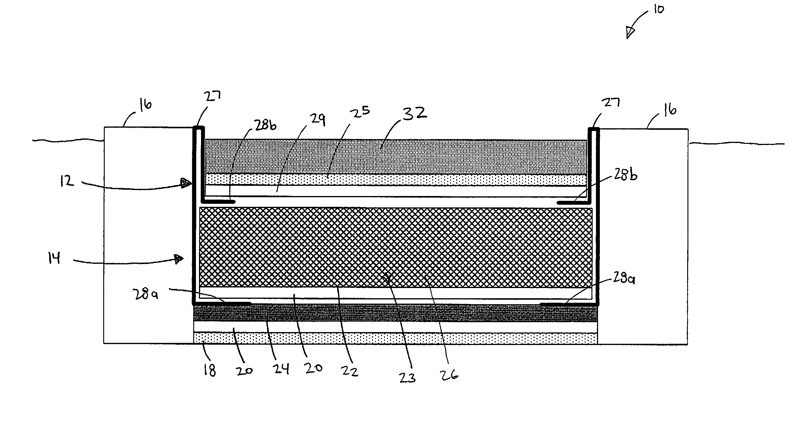
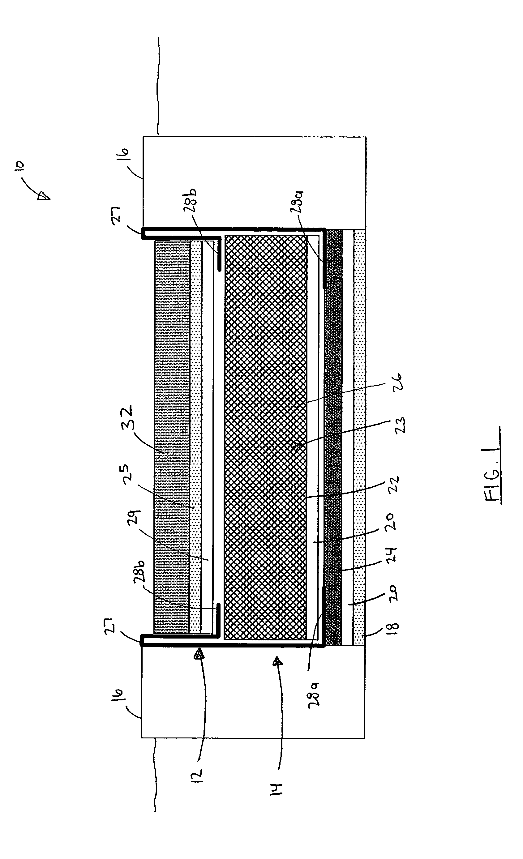
[0035]One example embodiment of an oil spill containment system constructed according to the present invention will now be described. The system in this example protects a transformer containing 12,000 liters of Voltesso 35 mineral oil. For this volume of oil, a containment area 8.5 meters long and 8.0 meters wide, and having a depth of 0.60 meters is excavated around and under the transformer. A containment basin 16 having retaining walls with a total height from the bottom of the excavated area of 0.70 m is built around the perimeter of the containment area. An impermeable liner 27 comprising a synthetic polymer is installed on the inside of the retaining walls.

[0036]The bottom of the containment basin 16 is then leveled off using sand. A 0.2 m high geosynthetic cell layer such as the Geoweb™ product from Presto Products Company (Appleton, Wis., USA) is then installed inside the containment basin 16, covering the bottom of the containment area. CHEMTEX™ granular co-polymer is then...

example 2

[0039]A second example embodiment of an oil spill containment system and an oil retention tray constructed according to the present invention will now be described. The system in this example protects a transformer which contains 12,000 liters of Voltesso 35 mineral oil and is suffering from a chronic oil leak from a failed flange. The rate of the leak is about 20 liters of oil per year. The oil spill containment system is built the same way as explained in Example 1, however it also includes an oil retention tray capable of capturing the oil from the leak.

[0040]The oil retention tray includes a frame constructed of wood, metal or other suitable construction material. The tray is 2 m long, 3 m wide and 0.20 m in height. The top of the frame is open, and the bottom is covered with a metal mesh. The bottom metal mesh allows rain water to percolate through the tray. The bottom of the oil retention tray is covered by an oil and water permeable membrane The sides of the tray are covered ...


PUM

PropertyMeasurementUnit
depthaaaaaaaaaa
depthaaaaaaaaaa
depthaaaaaaaaaa

Abstract

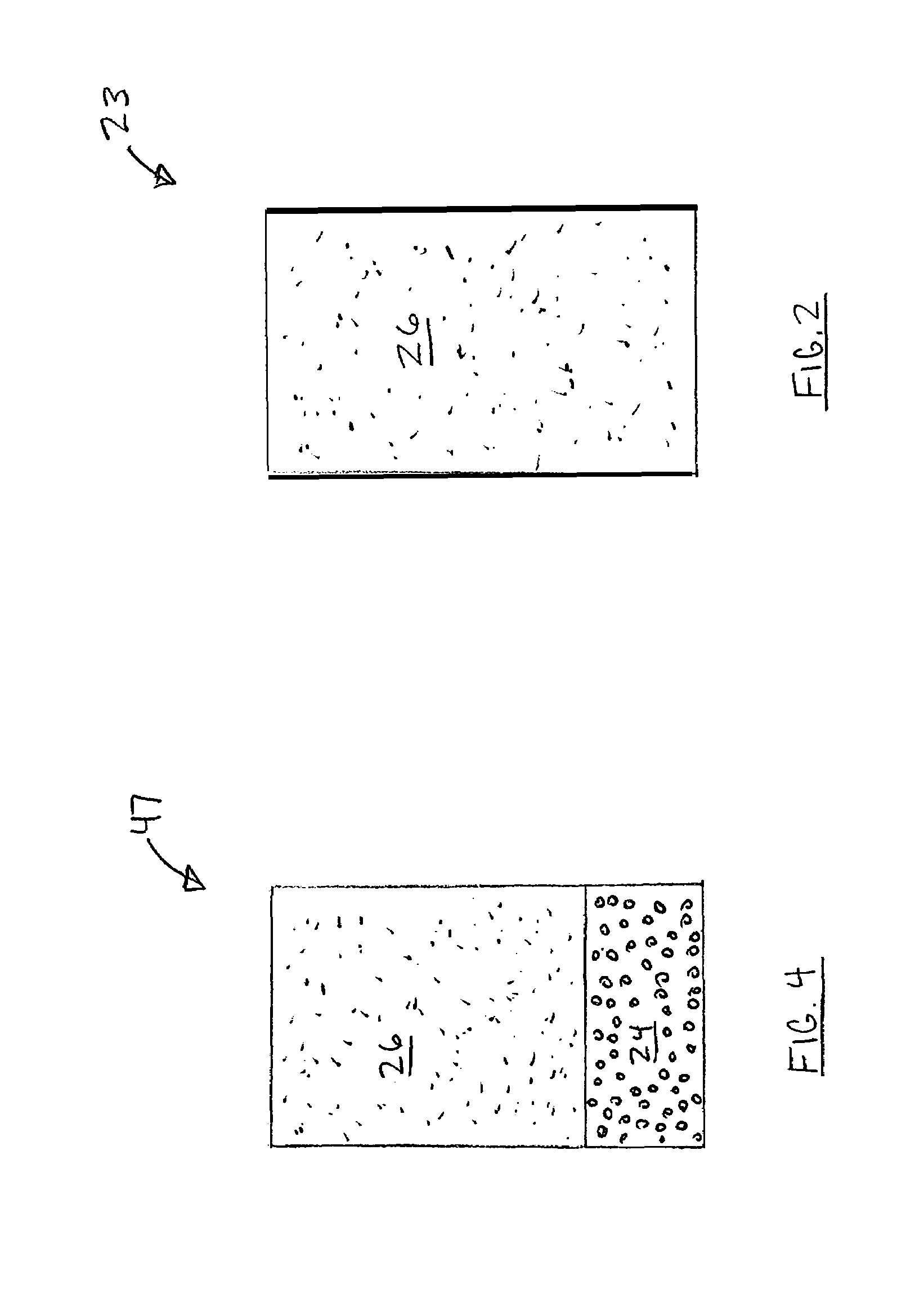
An oil spill containment system for containing oil spills or leaks from an oil containing vessel. In one embodiment, the oil spill containment system comprises a geosynthetic material defining a number of cells, with an oil absorbing material and an oil adsorbing material received in the cells of the geosynthetic material. This system contains oil which spills or leaks from the oil containing vessel while allowing water from rain or snow melt to permeate through the system.

Description

FIELD OF THE INVENTION[0001]The present invention relates to oil spill containment system, and more particularly to a method and apparatus for the containment of oil spills and leaks from oil containing equipment.BACKGROUND OF THE INVENTION[0002]Power transformers, capacitors, breakers and switches are electrical components extensively used by electrical utilities. With the notable exception of dry or gas-filled transformers, these electrical components typically contain insulating oil. Depending on the size of the electrical system, some of the transformers may contain several tens of thousand of liters of oil. As components of electrical transmission and distribution systems, these electrical components may be located within the limits of a transformer station, installed in remote locations, or located within a user's site or facility.[0003]Despite rigorous design and operational maintenance programs, failures of these electrical components occur. Catastrophic failures may result ...

Claims


Application Information

Patent Timeline
Patent Type & Authority Patents(United States)
IPC IPC(8): C02F1/28B01D17/022B32B1/00B32B27/00B65D90/24F16N31/00
CPCB32B27/00E04H5/04F16N31/002Y10S210/924B65D90/24B32B2307/726B32B2439/00B32B27/06
Inventor GONZALEZ, LUCIANO A.SIM, BLAIR F.TSANG, RON H. K.MLYNARCZYK, ALEXANDER Z.
Owner KINECTRICS INC
Learn More