Efficiency audible alarm

a technology of audible alarm and sound, which is applied in the direction of audible signalling, electric/electromagnetic signalling, instruments, etc., can solve the problem of small loss of efficient combination, and achieve the effect of doubling the sound energy output, ensuring the efficiency of sound production, and large tolerance for variability in manufactured devices

Inactive Publication Date: 2009-05-05
ADELMAN ROGER A
View PDF10 Cites 10 Cited by
  • Summary
  • Abstract
  • Description
  • Claims
  • Application Information

AI Technical Summary

Benefits of technology

[0005]The present invention describes a novel method for effectively doubling of the sound producing efficiency in fixed and multiple harmonic frequency types of plate and chamber and similar alarms, and it demonstrates practical means for achieving this improvement.
[0007]It is a primary objective of the present invention to provide a method for significantly improving the acoustic efficiency of a plate and chamber type of audible alarm by utilizing the vibrations that exist on both sides of the vibrating plate in a way that constructively combines the sounds so generated by both surfaces. Such constructive combination of sound is achieved by the addition of an acoustic pathway or pathways which first isolate sound generated in the resonating chambers from one another and then provide a differential acoustic delay such that the originally out of phase sounds combine together at the free air exit of each pathway in an additive fashion.
[0010]While there is great permissible latitude in the lengths of the conduits used to cause the constructive summation of the front and back generated sounds, it is an extremely important consideration of the present invention that its fundamental airborne sound producing structure is such that all of its parts are optimally chosen to support resonance at one or a small number of distinct frequencies. The so-designed alarm is specifically not intended to operate over a large frequency band, as would be the case, for instance, with audio speakers. The front and back chambers of the present invention, as well as the vibrating plate are all chosen with physical characteristics such that the sound is produced most efficiently, i.e. at the system resonance(s).
[0011]Such efficiency thus permits any of the attributes loudness, size, or power consumption to be optimized individually or collectively for a particular application while permitting very large tolerances for variability in manufactured devices.
[0012]This simple utilization of the heretofore “-unused” vibration surface on the backside of the vibrating member then permits a variety of application alternatives, particularly in the way that the sound phase-matching means are constructed. It is easily demonstrated that when the construction of the device is such that the original sound chamber and vibrating plate are caused to remain unchanged, the addition of a secondary resonating chamber and a precise phase matching means will result in a 6 dB increase in the output sound pressure level (SPL), i.e. a doubling of the sound energy output.

Problems solved by technology

The amount of loss of efficient combination is in fact quite small for even moderate variations from the ideal half wavelength.

Method used


Image

  • Efficiency audible alarm
  • Efficiency audible alarm
  • Efficiency audible alarm

Examples


Embodiment Construction

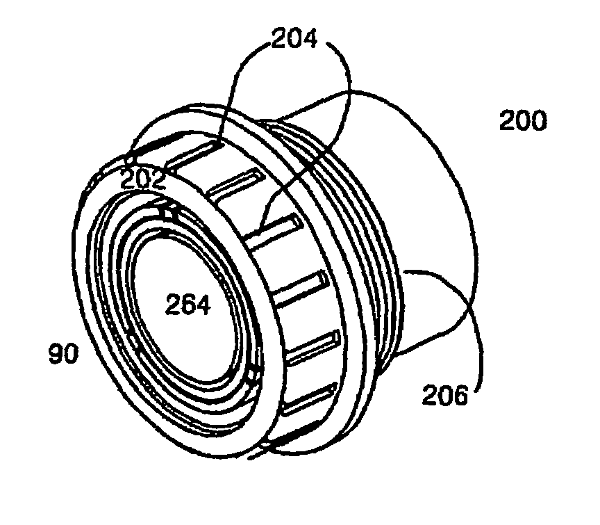
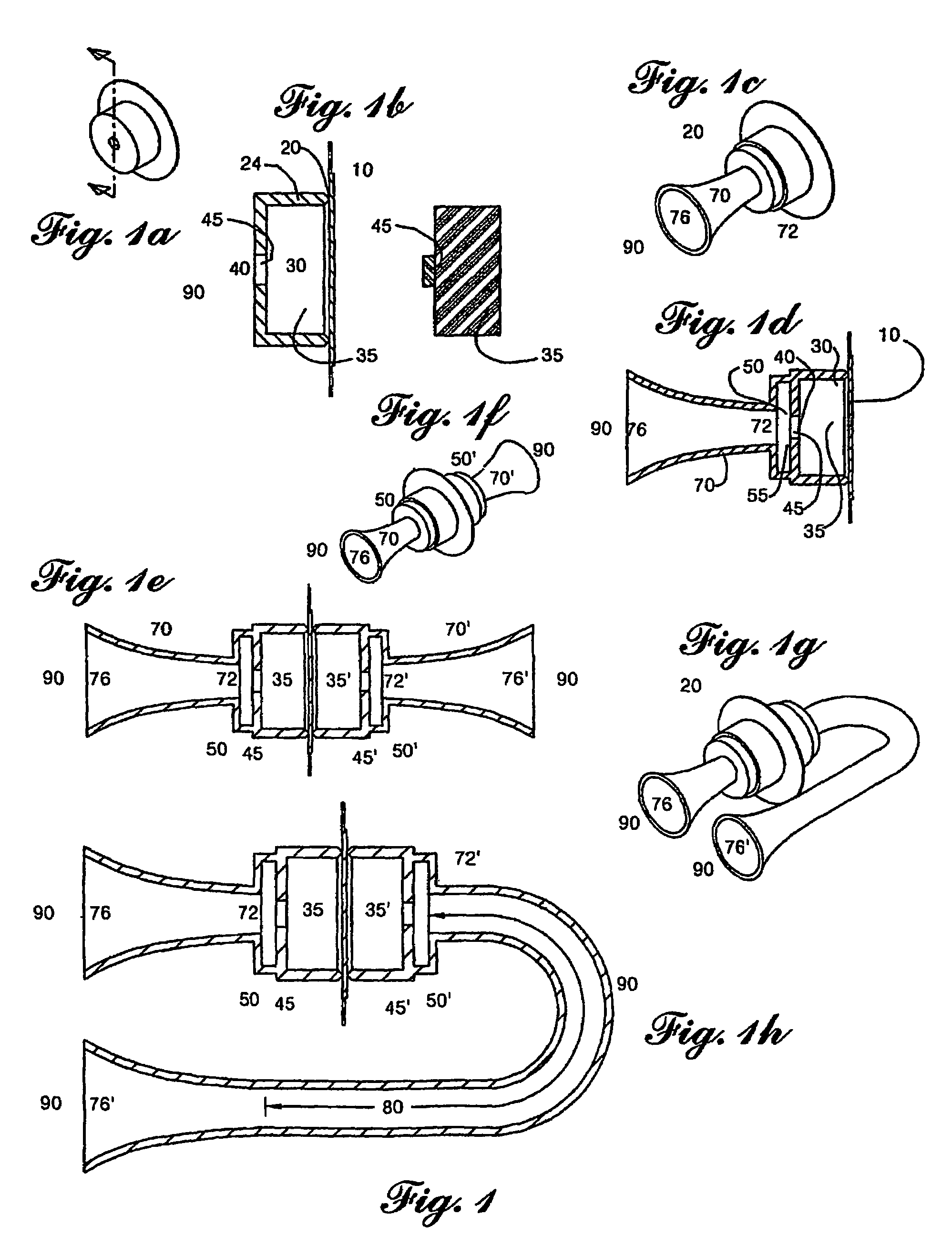
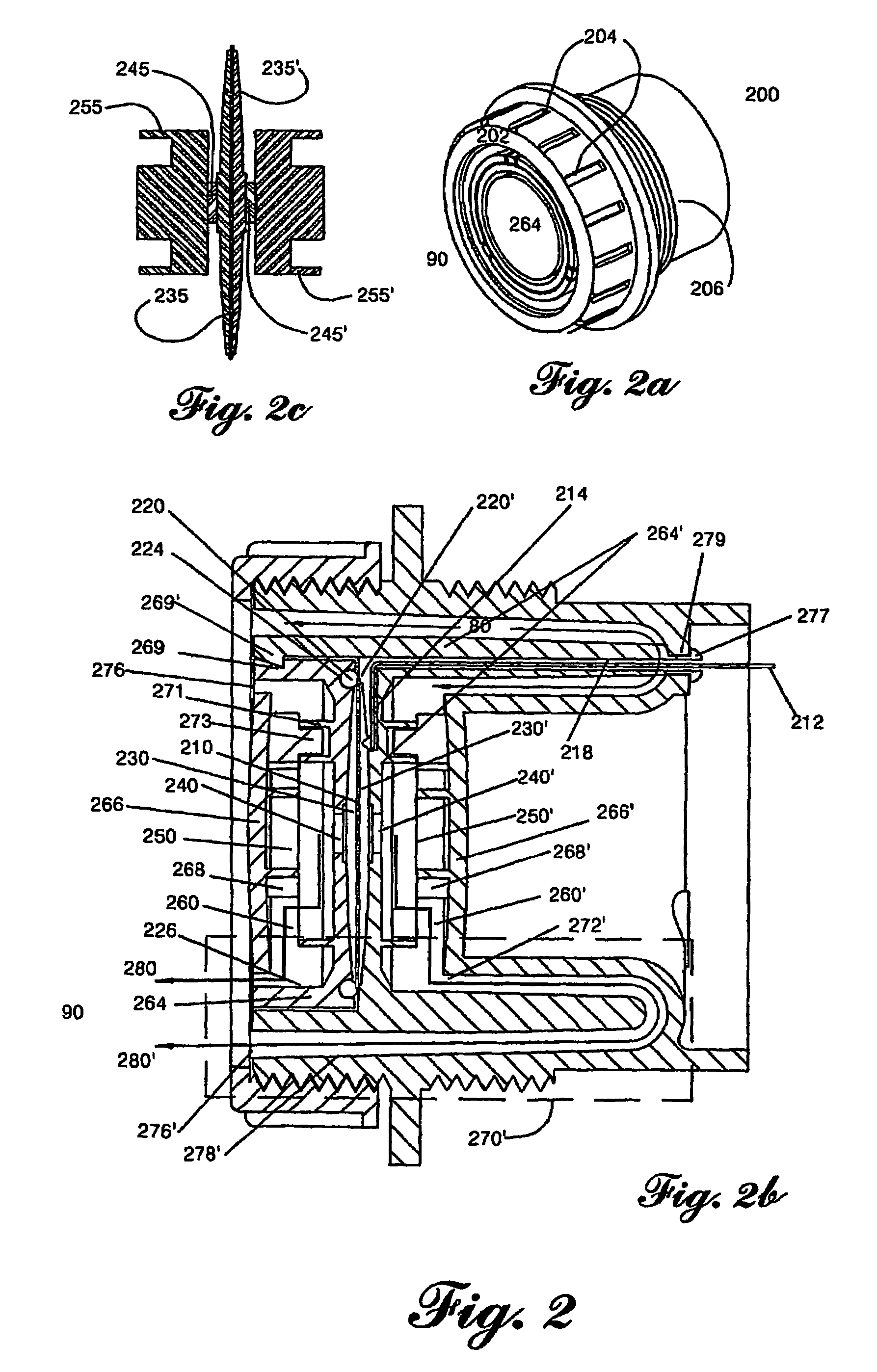
[0022]Referring now to the drawings, FIG. 1 depicts a progression of illustrative structures that demonstrate the theoretical basis for the invention. The particular aspects of the structures may be realized, of course, by geometries of different, equivalent constructions, e.g. a square instead of a circular boundary, or a magnetic instead of a piezoelectric drive, and the depictions of the FIGs must not be taken as limiting but rather simply a convenience for illustrating the principles in the invention.

[0023]Accordingly, FIG. 1a depicts the simple plate and chamber system which is further shown in cross section in FIG. 1b, and which comprises a transducer element 10 in intimate contact with a support feature 20 corresponding either to an edge or other vibration “node” of transducer element 10, said support feature then being extended to form a chamber wall 24 of resonance chamber 30 where the vibration of the transducer element 10 causes the springy air 35 (also more clearly depic...


PUM


Abstract

An audible alarm has first and second acoustic chambers that deliver sound to respective first and second horns. A phase adjustment circuit for delays the phase of sound generated in one of the two chambers so that sound emerging from the two horns is delivered with the same phase and same frequency, and emerging sound from the two horns is additive.

Description

RELATED APPLICATION[0001]This application claims priority to Provisional Application Ser. No. 60 / 431,560, filed Dec. 6, 2002 entitled Improved Efficiency Audible Alarm.BACKGROUND[0002]The present invention relates to the field of audible alarm devices in general, and in particular to that class of audible alarms that utilizes a driven vibrating member in conjunction with a resonance chamber to produce a loud sound roughly at a system resonant frequency and / or its multiples. The disclosed invention provides a general method for significantly improving the efficiency of sound production of such audible alarms, and it demonstrates several means for achieving such energy efficiency through example devices whose shape, structure and construction enable the realization of the method.[0003]The audible alarm is one of the most ubiquitous of all devices, and its manifestations range widely from the “clang” of a church bell to the “shriek” sound of a siren to the “click” sound of a tactile ke...

Claims


Application Information

Patent Timeline
Patent Type & Authority Patents(United States)
IPC IPC(8): G08B3/10G10K9/00G10K11/22G10K11/26
CPCG10K9/00G10K9/20G10K11/004G10K11/025G10K11/22G10K11/26
Inventor ADELMAN, ROGER A.
Owner ADELMAN ROGER A
Why Eureka
Try Eureka