Image pickup apparatus

a technology of image pickup and movable lens group, which is applied in the direction of instruments, television systems, lenses, etc., can solve the problems of deteriorating performance of movable lens group movement, affecting the quality of image extraction, so as to prevent deterioration of image quality and simple structure

Inactive Publication Date: 2009-05-05
SAMSUNG ELECTRONICS CO LTD +1
View PDF13 Cites 20 Cited by
  • Summary
  • Abstract
  • Description
  • Claims
  • Application Information

AI Technical Summary

Benefits of technology

[0007]The present invention eliminates the drawbacks of the above-described prior art by providing an image pickup apparatus which is simple in structure and which can prevent deterioration of the image quality, while providing a zooming effect substantially the same as that of an optical zoom lens system.
[0008]In the present invention, the mechanical structure and the lens structure are simplified by an appropriate combination of a bifocal optical system and a trimming (digital zoom) function, while providing the same zooming effect as a conventional optical zoom lens.
[0011]According to the above-described construction, the image quality of the trimmed image is less deteriorated.
[0013]The bifocal optical system provides a simpler lens construction and simplifies the surrounding mechanism thereof.
[0017]If the value of Dm exceeds the upper limit in condition (1), the image quality is unacceptably deteriorated due to trimming. If Dm is smaller than the lower limit in the condition (1), no sufficient zoom ratio can be obtained. If the relationship defined by the condition (1) is satisfied, it is possible to minimize a deterioration of the image quality due to trimming while providing a sufficient zoom ratio.

Problems solved by technology

Therefore, after the extracted image is enlarged to the same size of the original image, the extracted image becomes undesirably rough.
In a trimming system using an optical zoom lens, since it is necessary to provide a lens drive mechanism such as a motor or a cam in order to at least substantially continuously move the movable lens group, the lens drive mechanism tends to be complicated and large.
Furthermore, in an optical zoom lens, the movement of the movable lens group significantly deteriorates the performance due to decentering (eccentricity) thereof or the like.
In particular, such deterioration in the optical performance become more apparent as the optical zoom lens system is further miniaturized.
However, in a bifocal optical system, only two focal lengths can be selectively used, and hence, the bifocal optical system is not necessarily satisfactory for a zoom lens system.

Method used


Image

  • Image pickup apparatus
  • Image pickup apparatus
  • Image pickup apparatus

Examples


Embodiment Construction

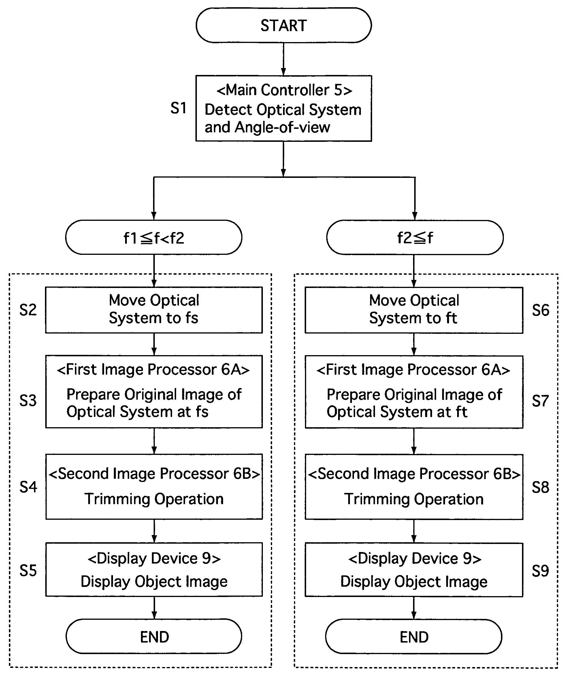
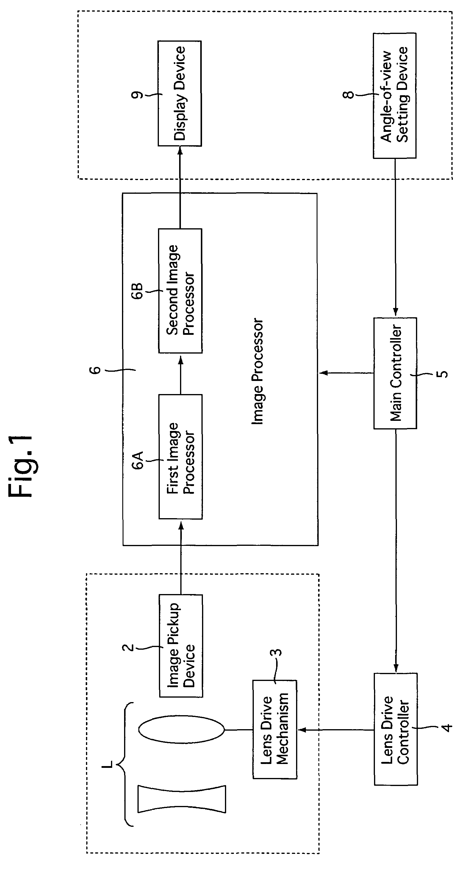
[0026]FIG. 1 shows a block diagram of main components of an image pickup apparatus according an embodiment of the present invention. The image pickup apparatus of this embodiment includes a multifocal optical system L, an image pickup device (CCD) 2, a lens drive mechanism 3, a lens drive controller 4, a main controller 5, an image processor 6, an angle-of-view setting device 8 and a display device (image monitor) 9.

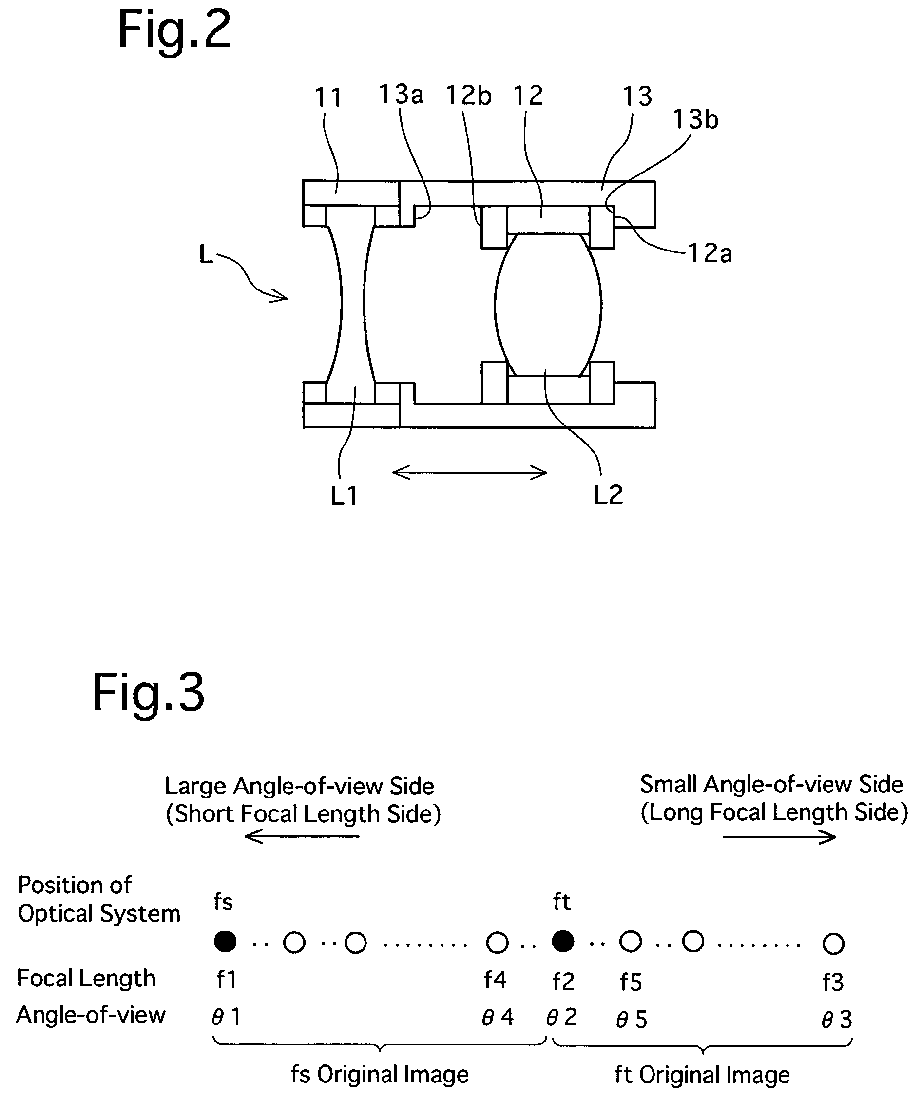
[0027]The multifocal optical system L is in the form of a bifocal lens having two variable different focal lengths f1 and f2 and includes at least one immovable lens group L1 and a movable lens group L2 which is movable relative to the immovable lens group L1, in that order from the object side, as shown in FIG. 2. The immovable lens group L1 is supported by a support frame 11 secured in the apparatus. The movable lens group L2 is supported by a support frame 12 held by the stationary frame 13. The stationary frame 13 is secured to the support frame 11 which supports the...


PUM


Abstract

An image pickup apparatus includes a multifocal optical system having at least two different focal lengths; an image pickup device for converting an optical image formed by the multifocal optical system into an image signal; a first image processor for forming an original image defined by an object image at each focal length of the multifocal optical system with the image signal received from the image pickup device; and a second image processor for trimming the original image formed by the first image processor. An object image of an angle-of-view corresponding to an intermediate focal length between the two focal lengths of the multifocal optical system is complemented by a trimmed image formed by the second image processor.

Description

BACKGROUND OF THE INVENTION[0001]1. Field of the Invention[0002]The present invention relates to an image pickup apparatus mounted to a small information terminal or the like.[0003]2. Description of the Related Art[0004]In recent years, small camera modules have been mounted in compact portable data handsets such as cellular phones and PDAs (Personal Digital Assistant). An optical system for such a small camera module must be small and particularly thin. To this end, in many cases, a unifocal lens system is used for the optical system to reduce thickness and a trimming (digital zooming) function is used to achieve a zooming effect. According to this trimming function, virtual telescopic photography (enlargement photography) can be carried out by trimming the angle-of-view (image capture range). Alternatively, a thin optical zoom lens system which does not utilize a trimming function has been proposed. This known optical zoom lens system is provided with at least one movable lens gro...

Claims


Application Information

Patent Timeline
Patent Type & Authority Patents(United States)
IPC IPC(8): H04N5/225
CPCG02B3/10G02B7/285G02B13/06G02B13/22G02B15/14G02B15/142
Inventor SAORI, MASAKAZUOGAWA, RYOTAOONO, MASAHIRO
Owner SAMSUNG ELECTRONICS CO LTD
Why Eureka
Try Eureka