Nuclear magnetic resonance imaging device

a technology of nuclear magnetic resonance and imaging device, which is applied in the field of nuclear magnetic resonance imaging device, can solve the problems of reducing reducing the strength of the mri signal, and arising problems, so as to reduce the infiltration of electromagnetic noise, reduce the quality of the acquired image, and reduce the strength

Inactive Publication Date: 2009-05-05
ESAOTE
View PDF14 Cites 34 Cited by
  • Summary
  • Abstract
  • Description
  • Claims
  • Application Information

AI Technical Summary

Benefits of technology

[0004]Particularly in MRI devices which are of the so called dedicated type, where the MRI scanner is relatively small so that the entire body of the patient cannot be housed inside the imaging cavity and also where the static magnetic field generated within the imaging cavity is of low or medium field strength, it is desirable to reduce the infiltration of electromagnetic noise inside the cavity and in the receiving coil. MRI signals are relatively low in strength and electromagnetic noise can reduce the quality of the acquired image. One solution known in the art to address this situation consists of at least reducing the opening of the imaging cavity by using electromagnetic shields which are grounded together with the electromagnetic shields provided in the scanner itself. Other kinds of shields have also been used. One optimum solution provides grounding the body of the patient under examination through the shields.
[0005]Devices having only one or two opposite openings for accessing the imaging cavity of the scanner can have simple solutions. However, problems arise when the scanner is not annular in shape. Scanners which have a “C-shape” or a “U-shape” have three open sides and it is particularly difficult to shield the imaging cavity of these devices. These kinds of MRI scanners allow different body parts of the patient to be positioned in the scanner. For positioning the different body parts in the scanner, different portions of the three open sides of the scanner are occupied by the patient so that a very flexible and also rapidly movable shielding member is needed.
[0006]The present invention provides for an MRI apparatus which has in combination a shielding member which can rapidly assume different configurations to partly close the open sides of the imaging cavity and with relatively simple devices. Furthermore, it is an object of the present invention to provide an MRI device having a shielding member which can maintain a temporary configuration for imaging a certain body part or anatomical region thereby reducing the time consuming process of closing the opening with an electromagnetic shield.

Problems solved by technology

MRI signals are relatively low in strength and electromagnetic noise can reduce the quality of the acquired image.
However, problems arise when the scanner is not annular in shape.
Scanners which have a “C-shape” or a “U-shape” have three open sides and it is particularly difficult to shield the imaging cavity of these devices.

Method used


Image

  • Nuclear magnetic resonance imaging device
  • Nuclear magnetic resonance imaging device
  • Nuclear magnetic resonance imaging device

Examples


Embodiment Construction

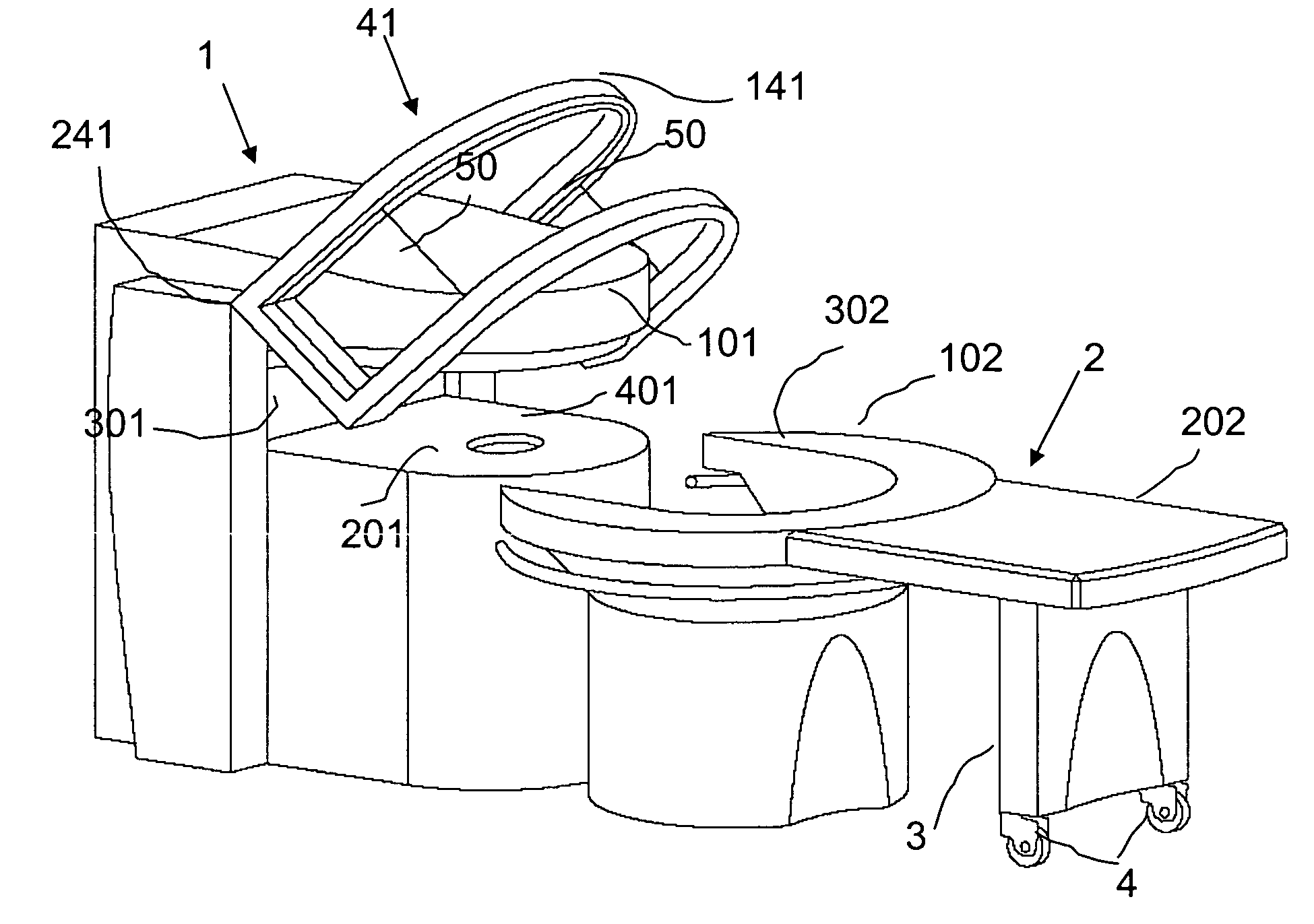
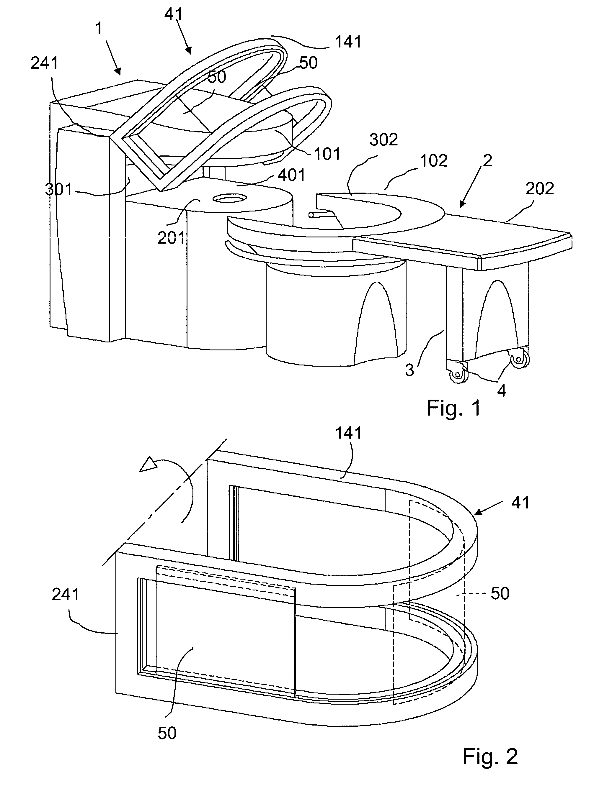
[0025]Referring to FIGS. 1 to 3, a Nuclear Magnetic Resonance Imaging device comprises a magnetic structure 1. The magnetic structure 1 shown in these figures is C-shaped and defines an imaging cavity with three open sides about its perimeter. The cavity is defined by an upper side 101, a lower side 201 and a vertical side 301. These three sides 101, 201, and 301 cover the magnetic structure and other operating members, and are made of an appropriate material, e.g. of plastic or the like, and the imaging cavity has a recess 401, in a predetermined area, for accommodating a fastening base of a receiving coil (not illustrated). The magnetic structure enclosed by the cover is formed by two spaced apart plates of ferromagnetic material and forms a yoke which is connected together by a vertical wall. Two poles covering an intermediate layer of magnetized material are supported to the inner sides of the horizontal plates.

[0026]The free end edges of the upper and lower sides 101 and 201 ar...


PUM


Abstract

A nuclear magnetic resonance imaging device has a magnetic structure which defines a cavity for housing at least part of the body of a patient with a magnetic field which permeates at least part of the cavity, an opening provides access to the imaging cavity from outside of the magnetic structure and electrically conductive and electrically grounded shielding provided at the opening is movable between a first inactive configuration wherein the opening is substantially open and an active configuration in which the opening is at least partially closed by the shielding.

Description

[0001]This application is a continuation-in-part of application Ser. No. 10 / 043,151 filed on Jan. 14, 2002, now U.S. Pat. No. 6,801,038, and which is a divisional of application Ser. No. 09 / 412,636 filed on Oct. 5, 1999, now U.S. Pat. No. 6,346,814.FIELD OF THE INVENTION[0002]The invention relates to a Nuclear Magnetic Resonance Imaging device having at least one rigid shielding member for at least partially closing one or more open sides, which can be moved between a first open position and a second (at least partially closed) position, the at least one rigid shielding member preferably being made of an electrically conducting material or coated with layers made of an electrically conducting material.BACKGROUND OF THE INVENTION[0003]An object of the present invention is to provide improvements in the electromagnetic shielding of MRI scanners by at least closing parts of the openings of the scanners which do not need to be open to allow the body under examination to access a cavity ...

Claims


Application Information

Patent Timeline
Patent Type & Authority Patents(United States)
IPC IPC(8): A61B5/055A61B6/04
CPCA61B5/0555A61B6/04G01R33/422A61B5/055A61B5/704
Inventor REZZONICO, FABIOCONTRADA, ORFEOSARASSO, GIANNI
Owner ESAOTE
Why Eureka
Try Eureka