Pre-cast concrete wall with truss ledge

Active Publication Date: 2009-05-12
SUPERIOR WALLS OF AMERICA
View PDF15 Cites 22 Cited by
  • Summary
  • Abstract
  • Description
  • Claims
  • Application Information

AI Technical Summary

Benefits of technology

[0009]It is an advantage of this invention that the floor trusses can be supported on the pre-cast concrete wall system at a below grade position.
[0010]It is another advantage of this invention that the pre-cast wall system can be manufactured at an off-site location in a manner that is consistent with the building

Problems solved by technology

In such situations, the use of the conventional pre-cast concrete wall system is hindered as the wall s

Method used


Image

  • Pre-cast concrete wall with truss ledge
  • Pre-cast concrete wall with truss ledge
  • Pre-cast concrete wall with truss ledge

Examples


Embodiment Construction

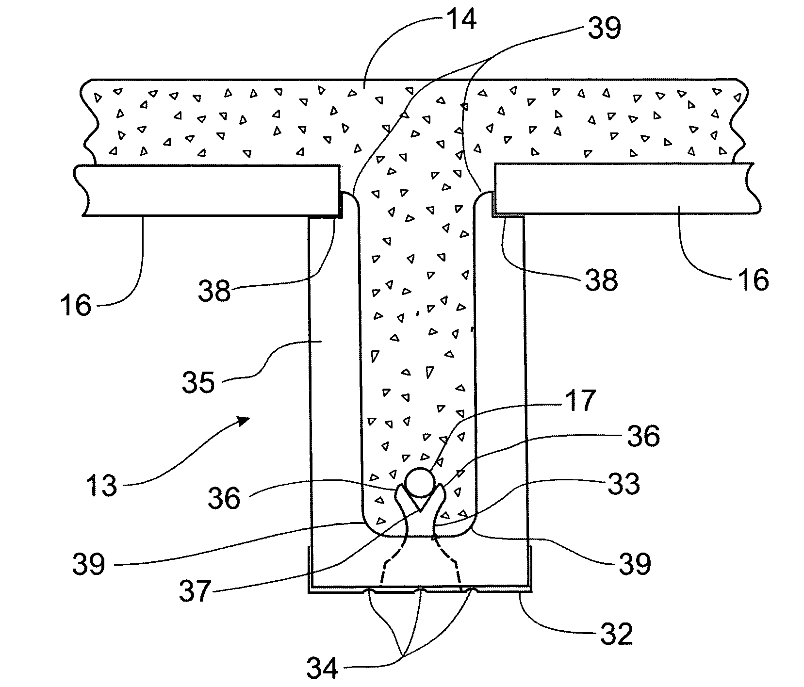
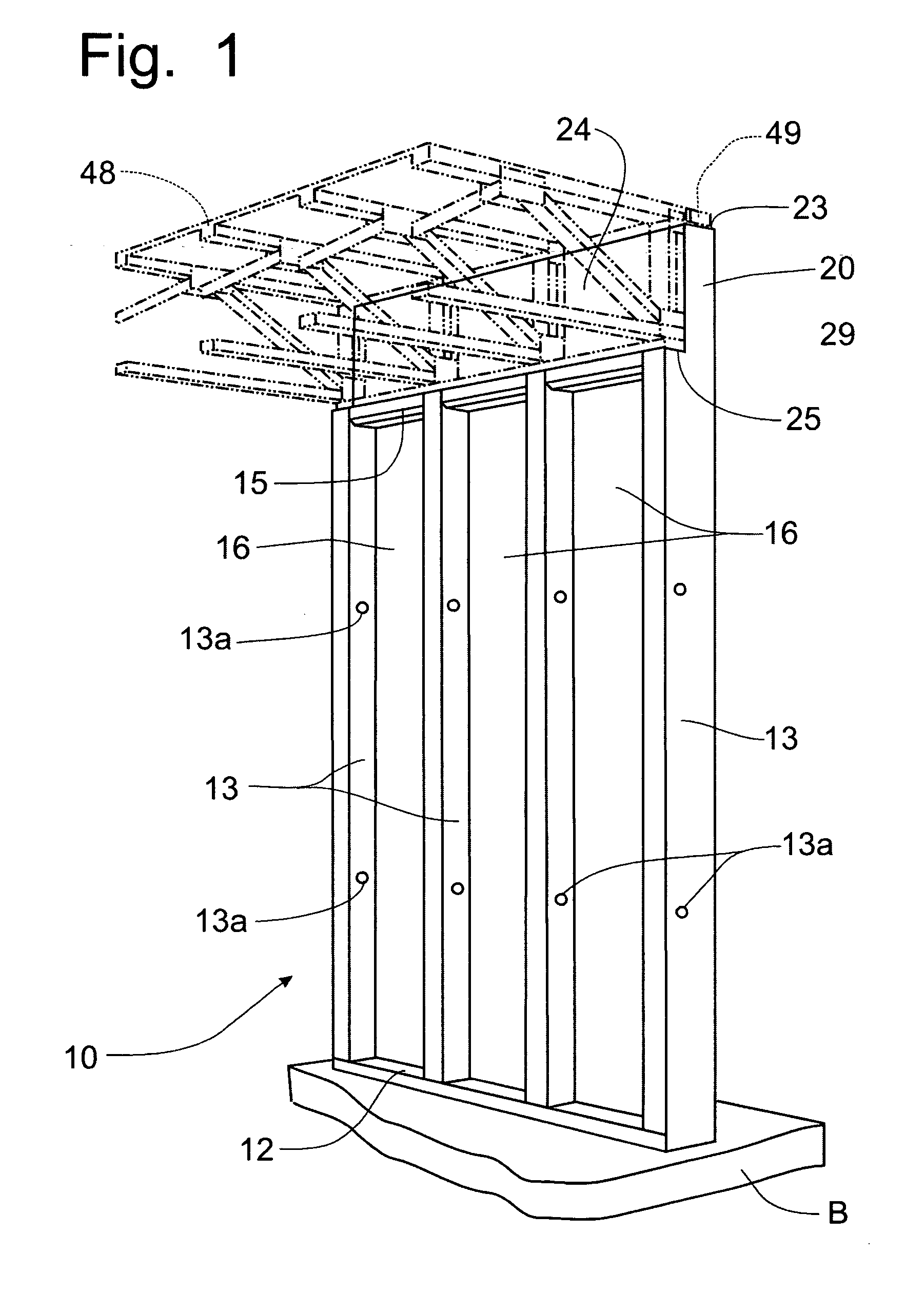
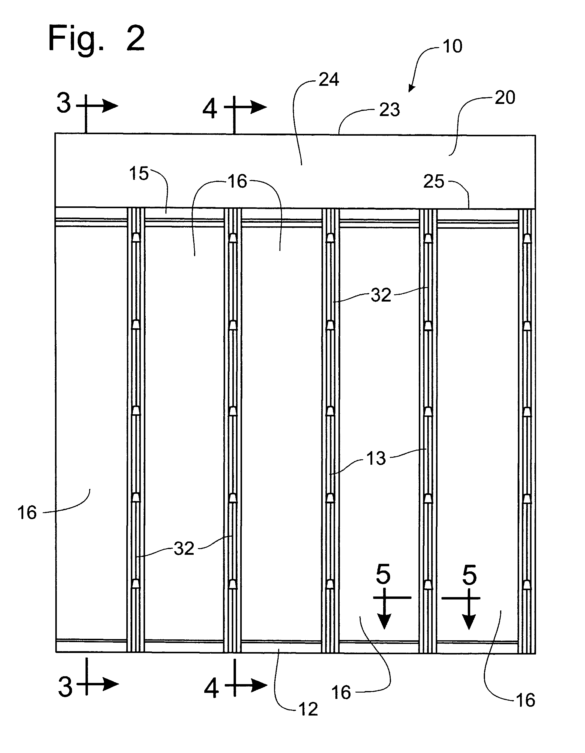
[0031]Referring to FIGS. 1-5, a pre-cast concrete wall system incorporating the principles of the instant invention can best be seen. The wall panel 10 is pre-cast in a form at a manufacturing plant, as is reflected in FIGS. 6 and 7 and will be described in greater detail below, and then transported when the concrete is cured to the job site for installation according to a known process involving the mounting of the walls 10 on a bed of crushed stone B and fastening the wall panels 10 together in a pre-arranged manner to form a basement or foundation wall on which a building will be subsequently erected. The wall panel 10 is formed with a generally horizontally oriented footer beam 12, an upper bond beam 15 oriented generally parallel to the footer beam 12, and a pre-defined number of generally vertical concrete studs 13 extending between the footer beam 12 and the upper bond beam 15. Between the concrete studs 13, the recessed wall shell 14 is insulated with a sheet of polystyrene ...


PUM

PropertyMeasurementUnit
Thicknessaaaaaaaaaa
Dimensionaaaaaaaaaa

Abstract

A pre-cast concrete wall system that incorporates a truss ledge for positioning a building floor system at a below-grade location. The truss ledge is defined by a vertical wall formed as a continuation of the exterior wall of the wall panel extending from the footer beam to the upper bond beam and projecting vertically above the upper bond beam to provide a support surface for the building floor members. A floor truss system can be supported on the upper bond beam with the truss ledge forming a concrete below-grade surface externally of the floor trusses. Galvanized steel stud facings incorporating fold-up reinforcing bar supports are used on the interior surface of the vertical wall beams. Insulated access holes are formed through the vertical beams for the passage of wiring and plumbing behind the wall finish to be fastened to the stud facings.

Description

BACKGROUND OF THE INVENTION[0001]The present invention relates generally to the pre-cast concrete wall systems and, more particularly, to a pre-cast concrete wall system that incorporates a support for a floor truss system.[0002]Pre-cast concrete wall systems are known in the art, as can be found, for example, in U.S. Pat. No. 6,494,004, issued to Melvin Zimmerman on Dec. 17, 2002. Such pre-cast concrete walls are typically used as basement walls for building structures, for example, houses and commercial buildings. Such walls are manufactured in a production plant by assembling non-concrete components into a form and pouring concrete into the form to encapsulate the non-concrete components. Once the concrete has hardened, the form is stripped away from the manufactured wall and the wall panel is transported to the job site for installation. Typically, a plurality of wall panels is assembled on the job site to form a basement structure of the building to be constructed thereon.[0003...

Claims


Application Information

Patent Timeline
IPC IPC(8): E04B1/00E04B1/74
CPCB28B19/003B28B23/0025E04B1/04
Inventor HARE, ROBERT W.ZIMMERMAN, MELVIN M.
Owner SUPERIOR WALLS OF AMERICA
Why Eureka
Try Eureka