Firearm muzzle brake

Inactive Publication Date: 2009-05-12
POFF CHARLES
View PDF19 Cites 22 Cited by
  • Summary
  • Abstract
  • Description
  • Claims
  • Application Information

AI Technical Summary

Benefits of technology

[0016]The muzzle brake of the present invention is effective in vertically directing gasses so as to depress the muzzle thereby counteracting muzzle jump, reducing normal recoil forces, and compensating from projectile induced torque thereby assisting in maintaining the weapon on target. The muzzle brake is further lightweight, readily adapted to various weapons systems and calibers, short in length so as to avoid adversely effecting the weapons accuracy and maneuverability,

Problems solved by technology

The act of firing such firearms is known to result in muzzle rise, and torque induced forces resulting in substantial displacement of the weapon from the original point of aim.
In addition, the rifling of the firearm barrel and resulting spin imparted on the bullet result in torque that also can cause the firearm to jump sideways.
Movement of the muzzle is undesirable for a number of reasons.
For example, in anticipation muzzle rise shooters have been known to flinch, r

Method used


Image

  • Firearm muzzle brake
  • Firearm muzzle brake
  • Firearm muzzle brake

Examples


Example

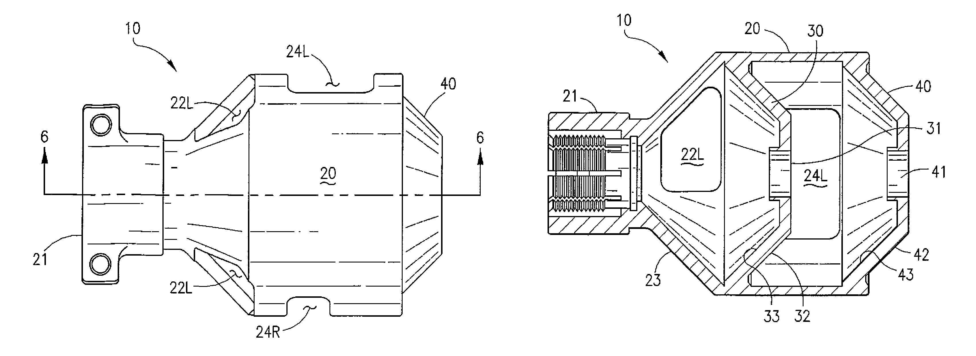
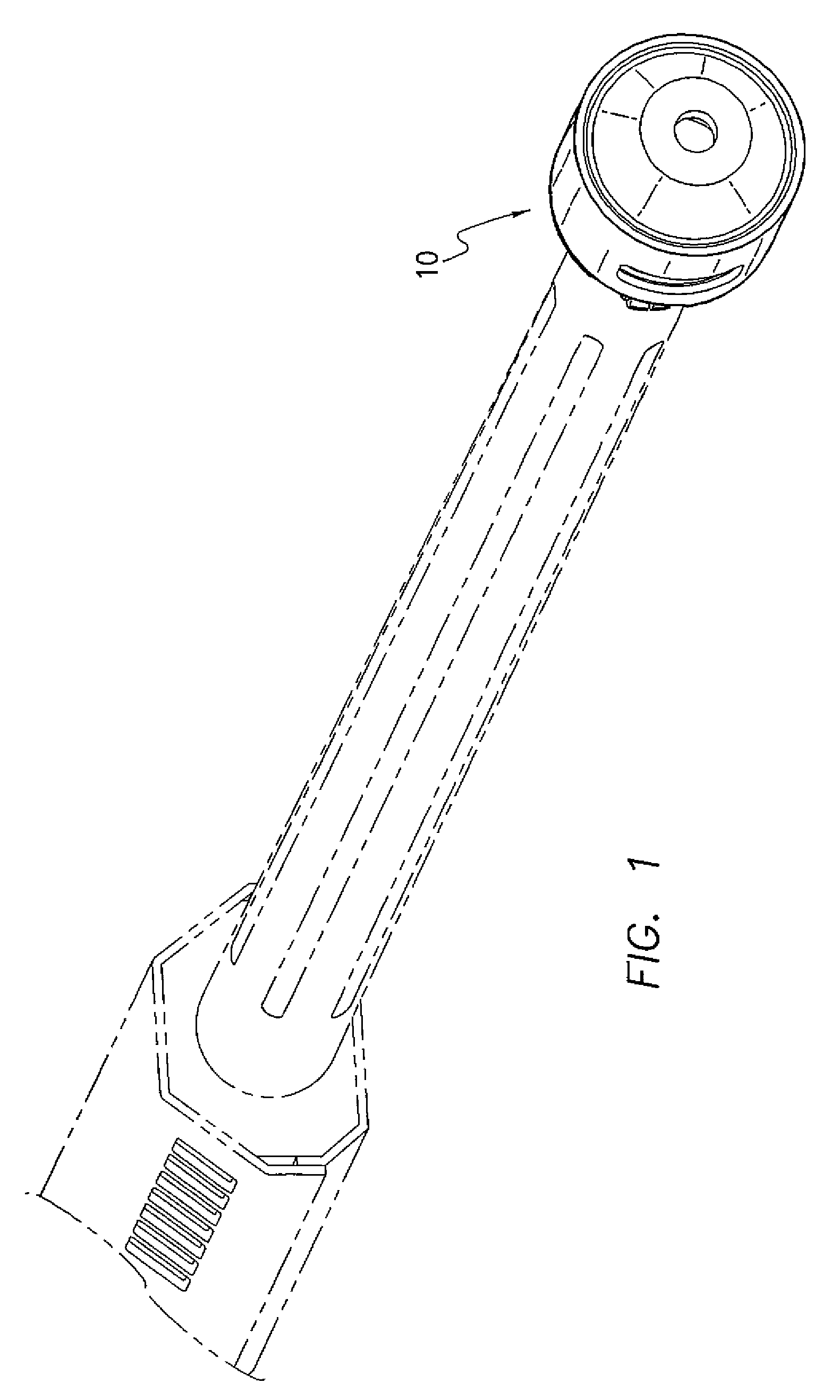
[0026]With reference now to the drawings, FIGS. 1-6 depict a muzzle brake 10 in accordance with the present invention. Muzzle brake 10 mounts on the firearm shown in phantom in FIG. 1 using the existing firearm's existing barrel muzzle threads, and may replace existing brakes or flash suppressors. Muzzle brake 10 is preferably fabricated from a suitable gunmetal material or alloy.

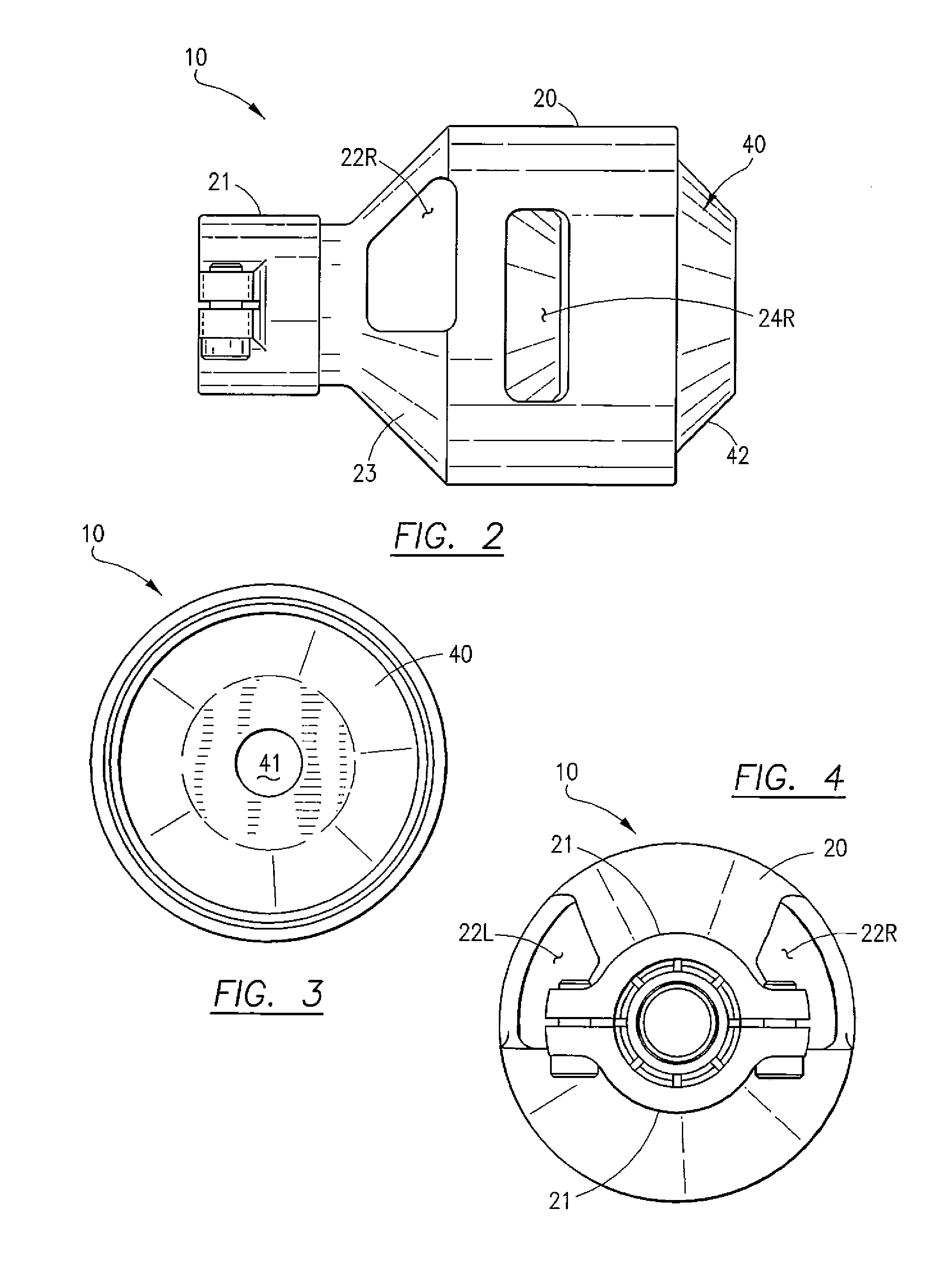
[0027]Muzzle brake 10 includes of three primary structural components, namely a main body 20, an internal baffle 30, and an end cap 40. Main body 20 has a mounting end 21 adapted for secured attachment to the end of the firearm barrel, either by threaded connection, or any other suitable connection method or structure. Internal baffle 30 and end cap 40 are shaped as generally identical truncated conical members. Internal baffle 30 defines a projectile aperture 31 and includes forward facing and rearward facing surfaces, referenced as 32 and 33 respectively. End cap 40 defines a projectile aperture 41, and i...


PUM


Abstract

A muzzle brake includes three primary structural components, namely a main body, a baffle, and an end cap. The components are preferably integrally fabricated into a single piece device, or alternatively may be fabricated separately and assembled. A muzzle brake in accordance with the present invention comprises a generally cylindrical muzzle brake assembly attachable to the muzzle end of a firearm. The muzzle brake assembly forms two expansion chambers, each of which is bounded by a peripheral sidewall defining opposing left and right vent apertures and a converging end wall. The end walls define axially aligned openings sized slightly larger than the diameter of the projectile for allowing the projectile to pass from the firearm muzzle, through the muzzle brake, and onward down the target line toward the intended target. The first chamber defines opposing left and right vent apertures for venting gases generally upward and rearward to reduce muzzle jump. The second chamber defines opposing left and right side apertures, with the left aperture being substantially larger than the right aperture for venting gases to counter torque related movement.

Description

CROSS REFERENCE TO RELATED APPLICATIONS[0001]This application claims the benefit of provisional U.S. Patent Application Ser. No. 60 / 699,239, filed Jul. 14, 2005.STATEMENT REGARDING FEDERALLY SPONSORED RESEARCH OR DEVELOPMENT[0002]N / ACOPYRIGHT NOTICE[0003]A portion of the disclosure of this patent document contains material that is subject to copyright protection. The copyright owner has no objection to the facsimile reproduction by anyone of the patent document or patent disclosure as it appears in the Patent and Trademark Office patent file or records, but otherwise reserves all rights whatsoever including copyrights.BACKGROUND OF THE INVENTION[0004]1. Field of the Invention[0005]The present invention relates to firearms and weapons, and, more particularly to firearms and weapons adapted to vent gases for reducing muzzle jump upon firing.[0006]2. Description of the Background Art[0007]The firing of projectiles, bullets, shot, and shells (hereinafter “projectile”) from firearms and ...

Claims


Application Information

Patent Timeline
IPC IPC(8): F41A21/34F41A21/36
CPCF41A21/36
Inventor POFF, CHARLES
Owner POFF CHARLES
Why Eureka
Try Eureka