
Machine for the production/processing of a material web and damping device

a technology of damping device and material web, which is applied in the direction of non-fibrous pulp addition, paper-making, coatings, etc., can solve the problems of high load, rapid wear of these components, and the diaphragm itself is subjected to intense continuous load, and achieves effective damping action and advantageous elastic properties.

Inactive Publication Date: 2009-05-12
VOITH PATENT GMBH
View PDF12 Cites 1 Cited by
  • Summary
  • Abstract
  • Description
  • Claims
  • Application Information

AI Technical Summary

Benefits of technology

The present invention provides a machine for damping pressure fluctuations in a treatment fluid, which can be done in a simple and cost-effective way. The invention involves the use of elastically deformable compensating material that can be placed in the fluid holding chamber or the line connection section of the machine. This material can absorb or damp the pressure fluctuations, reducing the impact on the treatment fluid. The compensating material can be compressed or expanded depending on the pressure fluctuations, and can be formed as a delimiting wall or a molding in the fluid holding chamber or the line connection section. The invention also provides a housing structure for the compensating material, which can be easily installed or retrofitted in the machine. The damping system can be designed to match the specific requirements of the machine. Overall, the invention provides a simple and flexible solution for damping pressure fluctuations in a treatment fluid machine.

Problems solved by technology

As a result of the pulsating operation of the valves and the associated intermittent transport of the treatment liquid from the water supply through the line connection to the nozzle moisteners, these components of the treatment section are continuously subjected to fast pressure fluctuations, which contribute to high loading and therefore to rapid wear of these components.
However, such oscillation dampers have the disadvantage that the edge of the diaphragm must be fixed to the housing in a liquid-tight and simultaneously stable manner and, particularly in this edge region, the diaphragm itself is subjected to intense continuous loading.
Furthermore, the gas chamber must be sealed off adequately from the outside and it is necessary for means to be provided for filling the gas chamber and for setting the gas pressure, so that the known oscillation damper is overall of relatively complicated construction.

Method used


Image

  • Machine for the production/processing of a material web and damping device
  • Machine for the production/processing of a material web and damping device
  • Machine for the production/processing of a material web and damping device

Examples


Embodiment Construction

[0051]The particulars shown herein are by way of example and for purposes of illustrative discussion of the embodiments of the present invention only and are presented in the cause of providing what is believed to be the most useful and readily understood description of the principles and conceptual aspects of the present invention. In this regard, no attempt is made to show structural details of the present invention in more detail than is necessary for the fundamental understanding of the present invention, the description taken with the drawings making apparent to those skilled in the art how the several forms of the present invention may be embodied in practice.

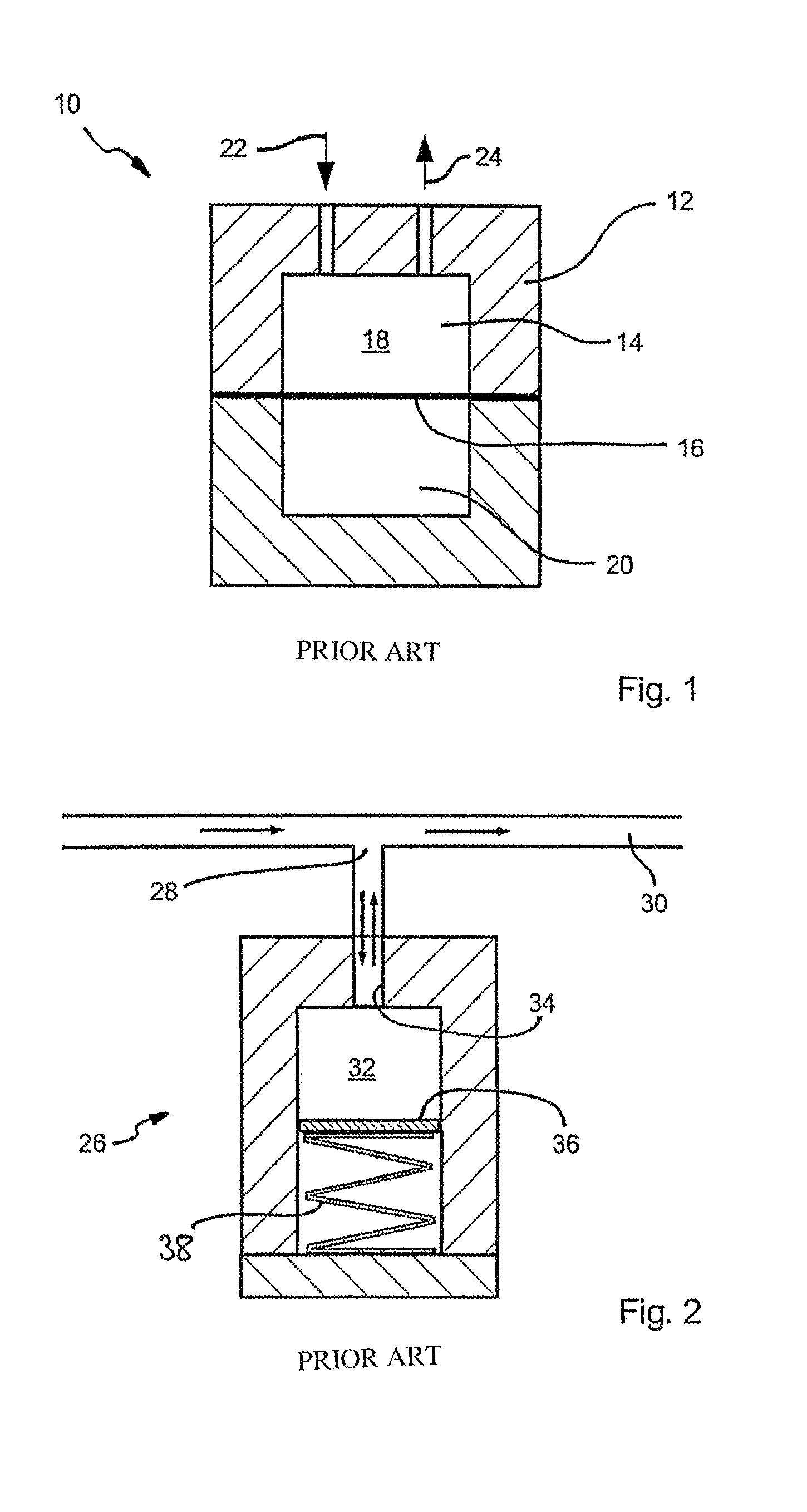
[0052]For the purpose of illustration, two examples of damping devices from the prior art are shown schematically in FIGS. 1 and 2. In FIG. 1, the damping device 10 comprises a housing structure 12, which encloses a hollow chamber 14. The hollow chamber 14 is subdivided by an elastic diaphragm 16 into a liquid chamber 18 ...


PUM

PropertyMeasurementUnit
Shore hardnessaaaaaaaaaa

Abstract

Machine for the production / processing of a material web, in particular a fibrous web, for example of paper or board, which comprises at least one treatment section in which the material web can have a treatment fluid applied to it, the treatment section being connected or able to be connected to a treatment fluid source via at least one line connection, an elastically deformable compensating material arranged in a fluid holding chamber of the treatment fluid source or of the treatment section. Alternatively, a damping device may be connected to the line connection or arranged in the latter and / or delimits such a fluid holding chamber, and / or elastically deformable compensating material which, in at least one section of the line connection, defines or co-defines an effective line cross section.

Description

CROSS-REFERENCE TO RELATED APPLICATIONS[0001]The present application claims priority under 35 U.S.C. 119 of German Patent Application No. 10 2005 008 071.5, filed on Feb. 22, 2005, the disclosure of which is expressly incorporated by reference herein in its entirety.BACKGROUND OF THE INVENTION[0002]1. Field of the Invention[0003]The present invention relates to a machine for the production / processing of a material web, in particular a fibrous web, for example of paper or board, which comprises at least one treatment section in which the material web can have a treatment fluid applied to it, the treatment section being connected or able to be connected to a treatment fluid source via at least one line connection.[0004]2. Discussion of Background Invention[0005]Machines of this type are known, for example from the papermaking industry. Normally, such machines comprise a plurality of treatment sections in which a treatment liquid is added to the material web. For instance, for the purp...

Claims


Application Information

Patent Timeline
Patent Type & Authority Patents(United States)
IPC IPC(8): D21H11/00
CPCD21F1/065D21G7/00
Inventor SCHMIDTKE, WERNER-MARCUS
Owner VOITH PATENT GMBH
Learn More