
System for predicting reduction in concentration of a target material in a flow of fluid

a technology of target material and fluid flow, which is applied in the direction of water treatment compound, water treatment parameter control, specific water treatment objectives, etc., can solve the problem that the time required for analysis of actual target contaminant concentration is typically too long to be practical for real-time control of fluid treatment system operating parameters, and the electrical energy used is one of the operating costs of these systems. problems, to achieve the effect of accurately predicting system performance, system parameters, and accurate relating system operating costs

Active Publication Date: 2009-05-12
TROJAN TECH
View PDF10 Cites 9 Cited by
  • Summary
  • Abstract
  • Description
  • Claims
  • Application Information

AI Technical Summary

Benefits of technology

This approach enables real-time control of ultraviolet fluid treatment systems, reducing operating costs by optimizing electrical energy and oxidant consumption based on measured fluid properties, thereby improving treatment efficiency.

Problems solved by technology

One of the operating costs is the electrical energy used to power the ultraviolet lamps.
The consumption of oxidant is another operating cost of these systems.
On rare occasions where feedback control has been used and measurements have been taken both upstream and downstream of the radiation zone, the time required for analysis of actual target contaminant concentration is typically too long to be practical for real-time control of the fluid treatment system operating parameters.
In addition, a reactor model relating system operating cost to electrical energy consumption and, where applicable, oxidant consumption has not been previously employed for ultraviolet fluid treatment system control.
Although kinetic models have been used to predict contaminant conversion, these models are based on measurements of the actual target contaminant concentration, not on more readily measured fluid properties that may be used to approximate system performance, and have not been linked with a reactor model to optimize system operating cost through control of system parameters.

Method used


Image

  • System for predicting reduction in concentration of a target material in a flow of fluid
  • System for predicting reduction in concentration of a target material in a flow of fluid
  • System for predicting reduction in concentration of a target material in a flow of fluid

Examples


example

[0167]A groundwater sample contaminated with trichloroethylene (TCE) was treated using a bench-scale recirculating batch photoreactor. The semi-batch UV reactor consists of a 32 L reservoir, a 6 L UV chamber housing a 12.4 watt low-pressure lamp and a recycle pump that draws the solution from the reservoir and pumps it to the UV chamber and back to the reservoir at a controlled flow rate of 110 liters per minute. A water-cooling jacket was mounted on the re-circulation pipe to maintain a constant temperature during the irradiation. The unit was provided with a sampling port, which allowed sampling of the solution at specific UV exposure times.

[0168]The test procedure comprised rinsing the apparatus with tap water and allowing it to completely drain, transferring 25 liters of the groundwater sample into the reservoir, adding the required amounts of hydrogen peroxide and TCE with the recirculation pump on, collecting the initial (t=0) sample, turning on the UV lamp and collecting subs...


PUM

PropertyMeasurementUnit
volumeaaaaaaaaaa
volumeaaaaaaaaaa
fluid propertiesaaaaaaaaaa

Abstract

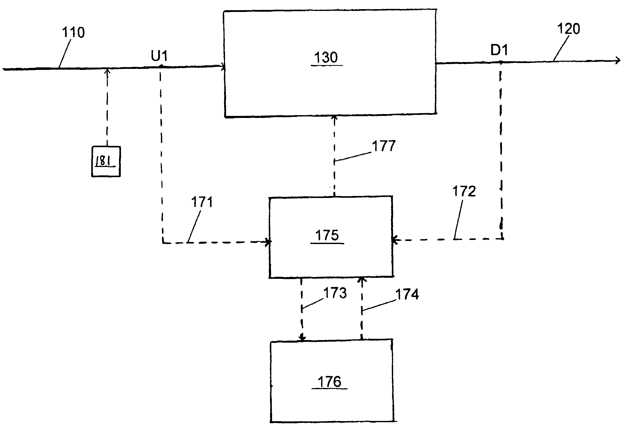
An ultraviolet fluid treatment system having feedback control using a kinetic model and a reactor model that interact with one another. The kinetic model uses readily measured fluid properties upstream and downstream of a radiation zone to calculate the conversion of a target contaminant as it passes through the fluid treatment system. This obviates the need to measure the contaminant concentration directly, which generally is too slow to permit real-time control. A reactor model relates system operating cost to system operating parameters, such as electrical power consumption and / or rate of oxidant addition, where applicable. The reactor model is linked to the kinetic model and is used to optimize operating cost by adjusting system operating parameters based on a comparison between the conversion obtained from the kinetic model and the overall treatment objectives. A control center, an ultraviolet fluid treatment apparatus, and a method of treating a fluid are also disclosed.

Description

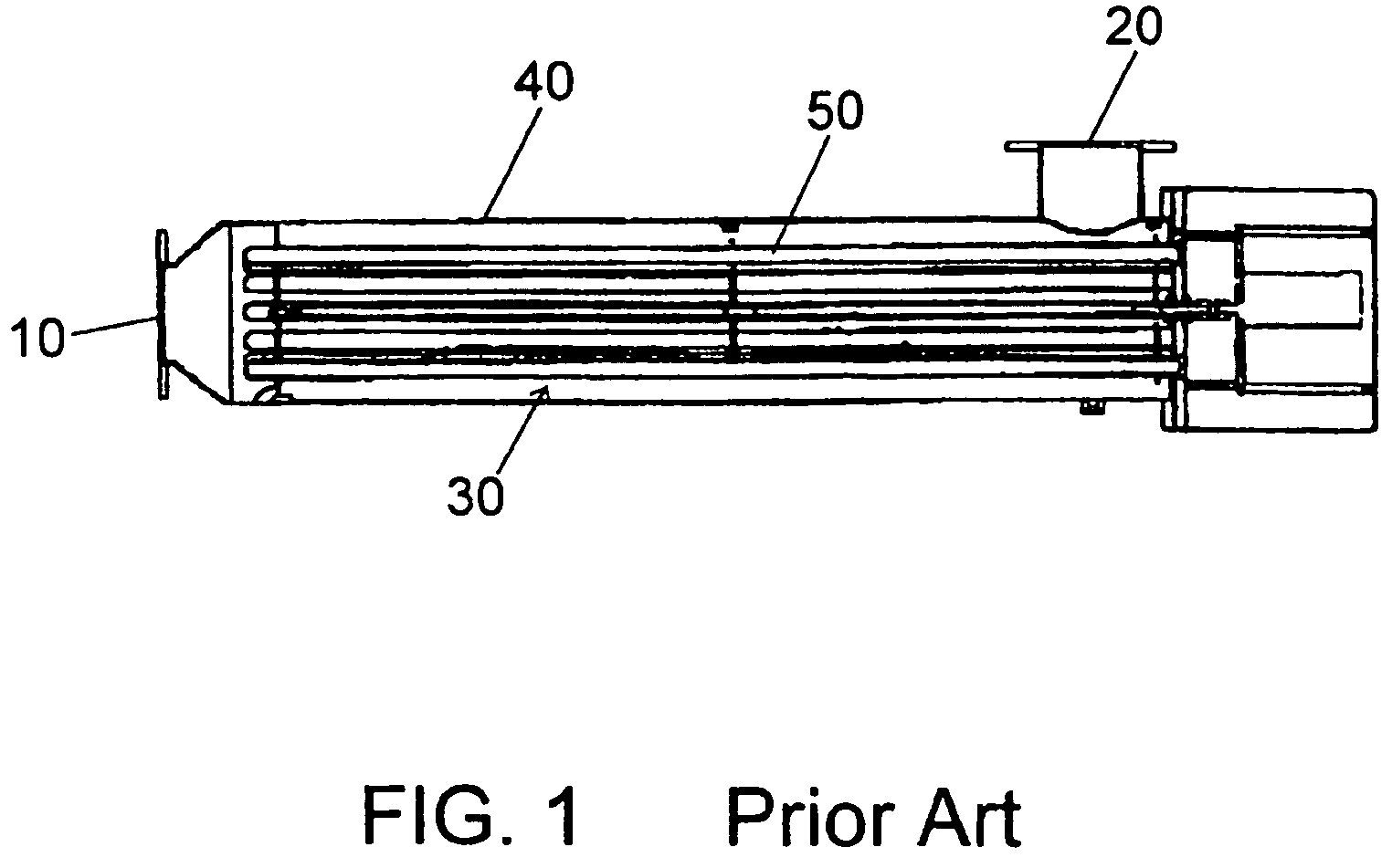
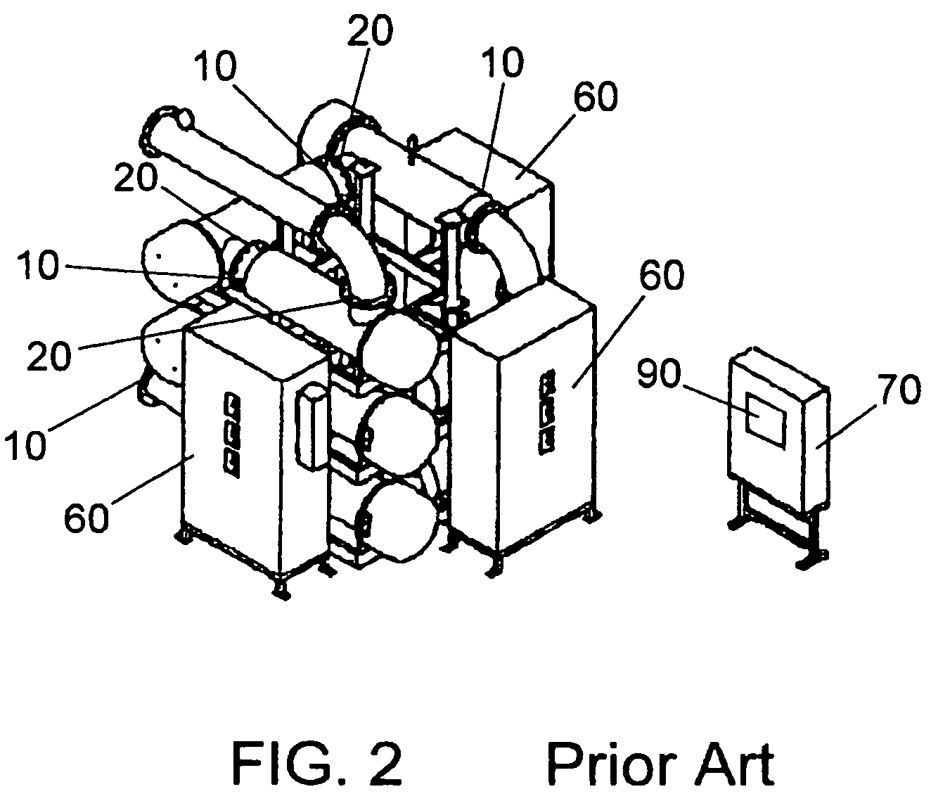
CROSS-REFERENCE TO RELATED APPLICATION[0001]The present application claims the benefit under 35 U.S.C. §119(e) of provisional patent application Ser. No. 60 / 551,350, filed Mar. 10, 2004, the contents of which are hereby incorporated by reference.BACKGROUND OF THE INVENTION[0002]1. Field of the Invention[0003]The invention relates to a radiation (e.g., ultraviolet radiation) fluid treatment systems and to a method for radiation (e.g., ultraviolet radiation) treatment of a fluid. More particularly, in a preferred embodiment, the invention relates to a treatment system which is controllable using both a kinetic model and a reactor model that interact with one another.[0004]2. Description of the Prior Art[0005]Ultraviolet fluid treatment systems are used, for example, in the disinfection or other treatment of fluids contaminated with microorganisms and in the oxidation and degradation of chemical contaminants. A variety of ultraviolet fluid treatment devices are used in these systems. S...

Claims


Application Information

Patent Timeline
Patent Type & Authority Patents(United States)
IPC IPC(8): C02F1/32C02F1/42A61L2/10A61L2/24A61L2/28C02F1/00C02F1/72
CPCA61L9/205C02F1/008C02F1/32C02F1/722C02F2101/32C02F2101/34C02F2101/36C02F2101/38C02F2103/06C02F2201/3227C02F2201/326C02F2209/001C02F2209/003C02F2209/04C02F2209/05C02F2209/06C02F2209/08C02F2209/10C02F2209/20C02F2209/23C02F2209/40C02F2303/04C02F2305/023C02F2305/10Y02W10/37
Inventor WILLIAMSON, CHRISTIANROYCE, ALANSTEFAN, MIHAELA I.
Owner TROJAN TECH
Learn More