Vehicular transmission

a technology of transmission and transmission shaft, applied in the direction of gearing control, gearing element, belt/chain/gearing, etc., can solve the problem of clutch sliding, and achieve the effect of reducing manufacturing cost, fuel economy improvement, and improving durability

Inactive Publication Date: 2009-05-19
HONDA MOTOR CO LTD
View PDF11 Cites 4 Cited by
  • Summary
  • Abstract
  • Description
  • Claims
  • Application Information

AI Technical Summary

Benefits of technology

[0010]According to the present invention, the pressure inside the intake pipe is estimated on the basis of the rotational speed at the output shaft of the engine and the opening of the throttle valve for a predetermined time while the cylinders that have been deactivated are being reinstated, and then the driving torque generated by the engine is estimated on the basis of these rotational speed and estimated pressure. This estimated driving torque by the engine never becomes excessively large, so the hydraulic pressure that is set in correspondence to this driving torque will never be set higher than necessary. Therefore, the hydraulic pump is protected against being driven excessively or wastefully, so fuel economy is improved. As the increase in the hydraulic pressure is restricted in this way, the durability of the transmission is also improved, so it is even possible to design the transmission in a lighter body and to lower the manufacturing cost.
[0011]If the pressure of the intake pipe is estimated from the opening of the throttle valve as in this case, then the precision at which the driving torque of the engine is estimated can be a little imprecise. However, this does not present any problem because the estimated driving torque and the transmitted torque of the frictionally engaging device, which is in loose engagement, are compared, and the larger of the two, i.e., the estimated driving torque and the transmitted torque, is used for setting the pressure applied in operational control of the ratio change mechanism. This method allows the lower limit of the driving torque to be set by the transmitted torque of the frictionally engaging device. As a result, a prevention can be provided against any harmful effect that may otherwise arise if the driving torque of the engine is estimated lower than actual.
[0012]If the ratio change mechanism preferably comprise a belt-type continuously variable transmission, which includes a V-belt disposed around a drive pulley and a driven pulley, then the hydraulic pressures applied to the pulleys never become excessively high. This prevents the V-belt from being pushed by forces that are larger than necessary, so the durability of the V-belt will be improved.

Problems solved by technology

Because the clutching capacity is limited to the minimum necessary for the transmission of the engine-output torque, the clutch can slip limiting the torque change while the output of the engine or the load of the driving vehicle is changing rapidly (for example, when the accelerator pedal is operated quickly or the vehicle goes over a curb).

Method used


Image

  • Vehicular transmission
  • Vehicular transmission
  • Vehicular transmission

Examples


Embodiment Construction

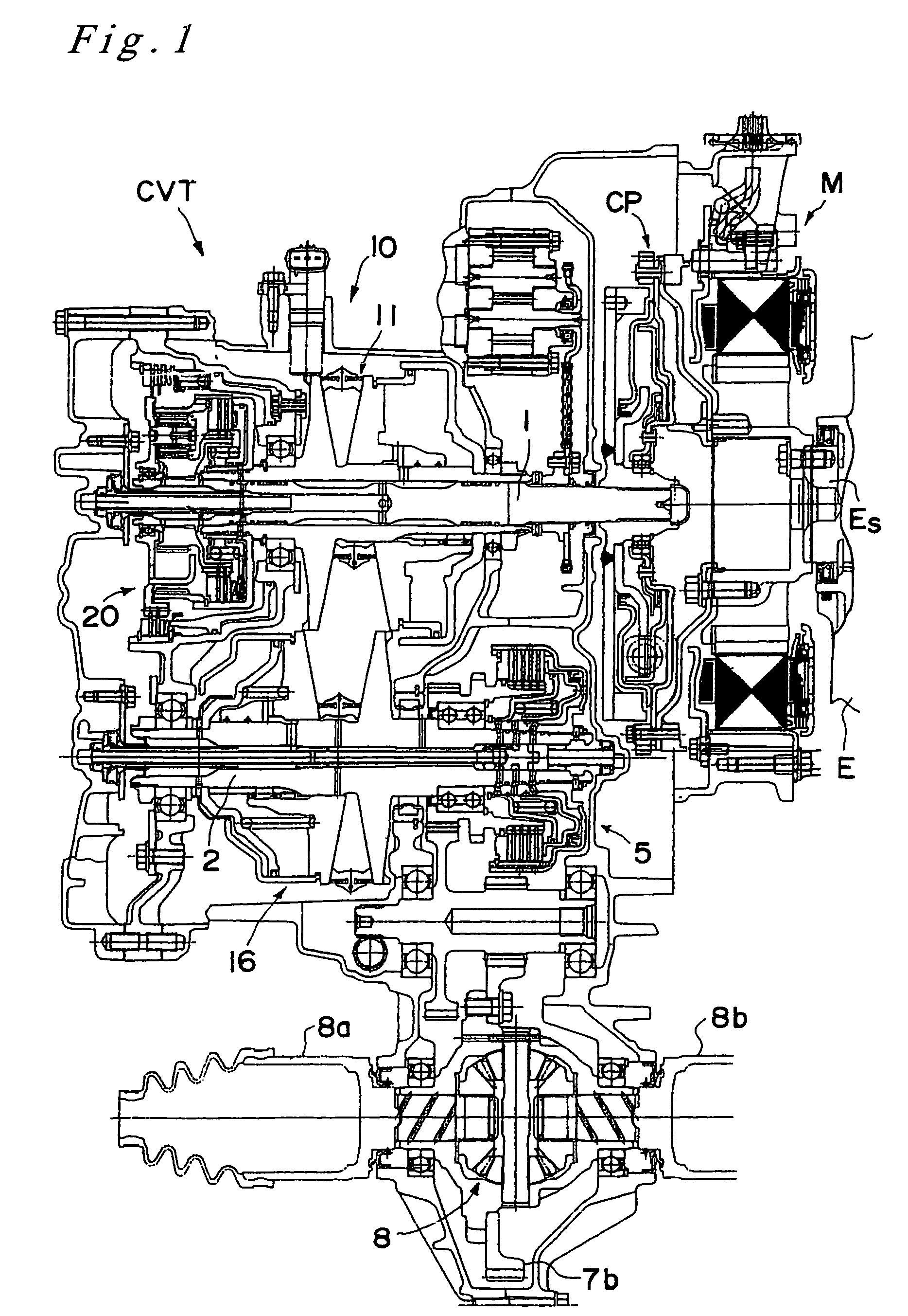
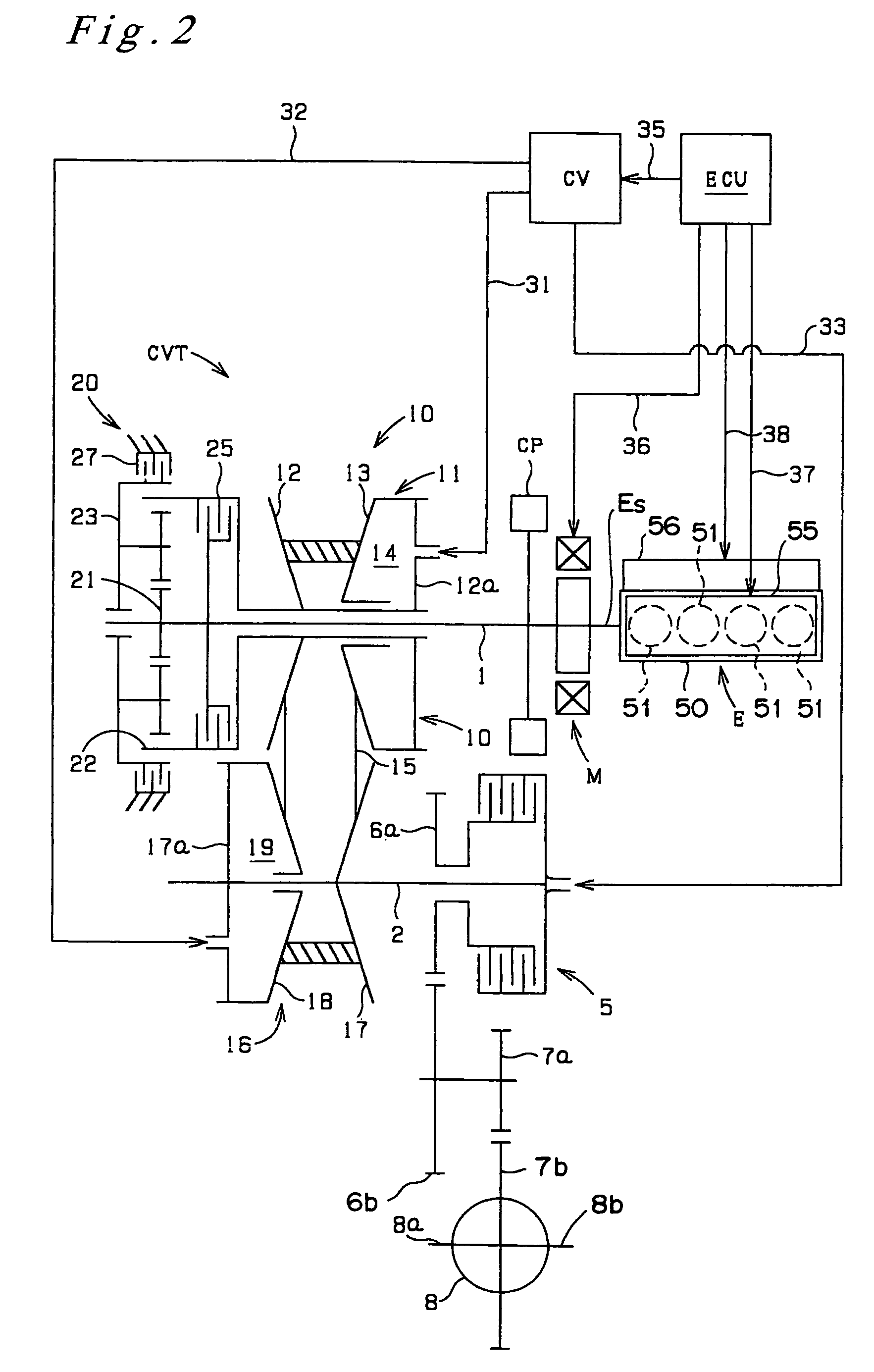
[0019]A preferred embodiment according to the present invention is described in reference to the drawings. FIG. 1 is a sectional view describing the construction of a vehicular transmission according to the present invention, and FIG. 2 shows the transmission system of this transmission. It is clear from these drawings that this transmission comprises an engine E, an electrical motor generator M, which is disposed on the output shaft Es of the engine E, and a continuously variable transmission CVT, which is connected through a coupling mechanism CP to the output shaft Es of the engine.

[0020]The engine E is a four cylinder reciprocating engine and has a piston 52 (refer to FIG. 3) in each of the four cylinder bores 51 formed in a cylinder block 50. The engine E is also equipped with a suction and exhaust controller 55, which controls the operation of the suction valve 53 and the exhaust valve 54 (refer to FIG. 3) for each cylinder bore 51, and equipped with a fuel injection and ignit...


PUM


Abstract

A vehicular transmission comprises an electrical control unit ECU, which controls to bring a starting clutch into loose engagement for a predetermined time while a deactivated cylinder mode is being terminated. The electrical control unit also estimates, during this predetermined time, an estimated PB, which is an estimated pressure inside the intake pipe, on the basis of a rotational speed Ne at the output shaft of the engine and of an opening TH at the throttle valve, and it then estimates or calculates the driving torque generated by the engine on the basis of this estimated PB and the rotational speed Ne. From this calculated driving torque, the electrical control unit sets respective pressures to be applied to a drive pulley and a driven pulley, which constitute a continuously variable transmission CVT.

Description

FIELD OF THE INVENTION[0001]The present invention relates to a vehicular transmission that transmits the driving force of an engine comprising a plurality of cylinders, to wheels through a ratio change mechanism. Furthermore, the present invention relates particularly to a vehicular transmission that is characterized by a control of a hydraulic pressure applied for the operation of the ratio change mechanism.BACKGROUND OF THE INVENTION[0002]Many automobiles are equipped with a transmission that generally includes such a ratio change mechanism, whose operation is controlled by applying a predetermined pressure of hydraulic oil (line pressure). For example, Japanese Laid-Open Patent Publication No. S60(1985)-256662 discloses a system that applies a hydraulic pressure into a hydraulic cylinder for controlling the width of a pulley, or more specifically, the force applied on the pulley pushing the belt in a belt-type continuously variable transmission. This control system operates to ca...

Claims


Application Information

Patent Timeline
Patent Type & Authority Patents(United States)
IPC IPC(8): B60W10/00F16H59/30
CPCF16H59/14F16H61/66272F16H59/30F16H59/36F16H59/76Y10T477/693F16H2061/6618Y10T477/6403F16H61/0021
Inventor EGUCHI, TAKAHIROTAKEMORI, YUICHIROUNEYAMA, TOSHIKAZU
Owner HONDA MOTOR CO LTD
Why Eureka
Try Eureka