
Weighing system of monolithic construction including flexural pivot

a monolithic construction and weighing system technology, applied in the field of weighing systems, can solve the problems of not providing flexural pivots for mounting transmission levers, but individual vertical springs, and cannot replace flexural pivots, etc., to achieve the effect of improving flexural pivots, no hysteresis, and simple manufacturing

Active Publication Date: 2009-05-19
SARTORIUS LAB INSTR GMBH & CO KG
View PDF20 Cites 16 Cited by
  • Summary
  • Abstract
  • Description
  • Claims
  • Application Information

AI Technical Summary

Benefits of technology

[0008]It is therefore an object of the invention to provide an improved flexural pivot for a weighing system of the above-described type, which is simple to manufacture and, to the extent possible, shows no hysteresis.SUMMARY OF THE INVENTION
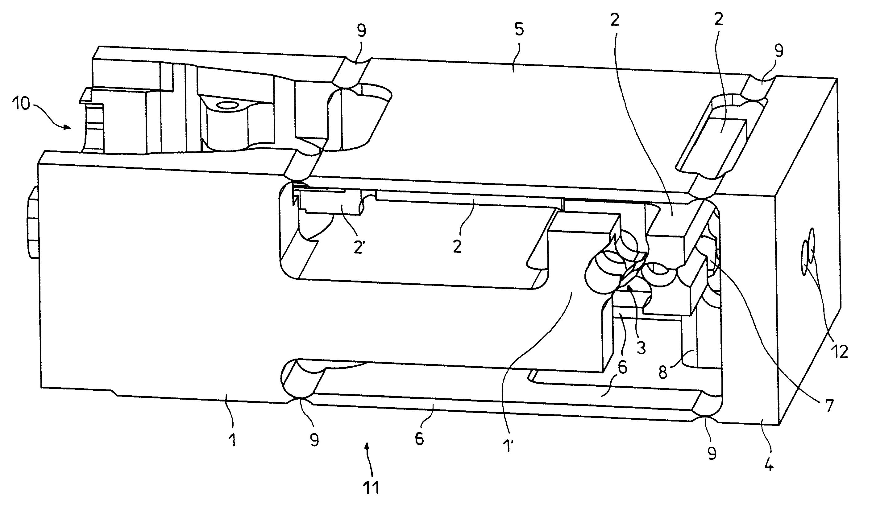
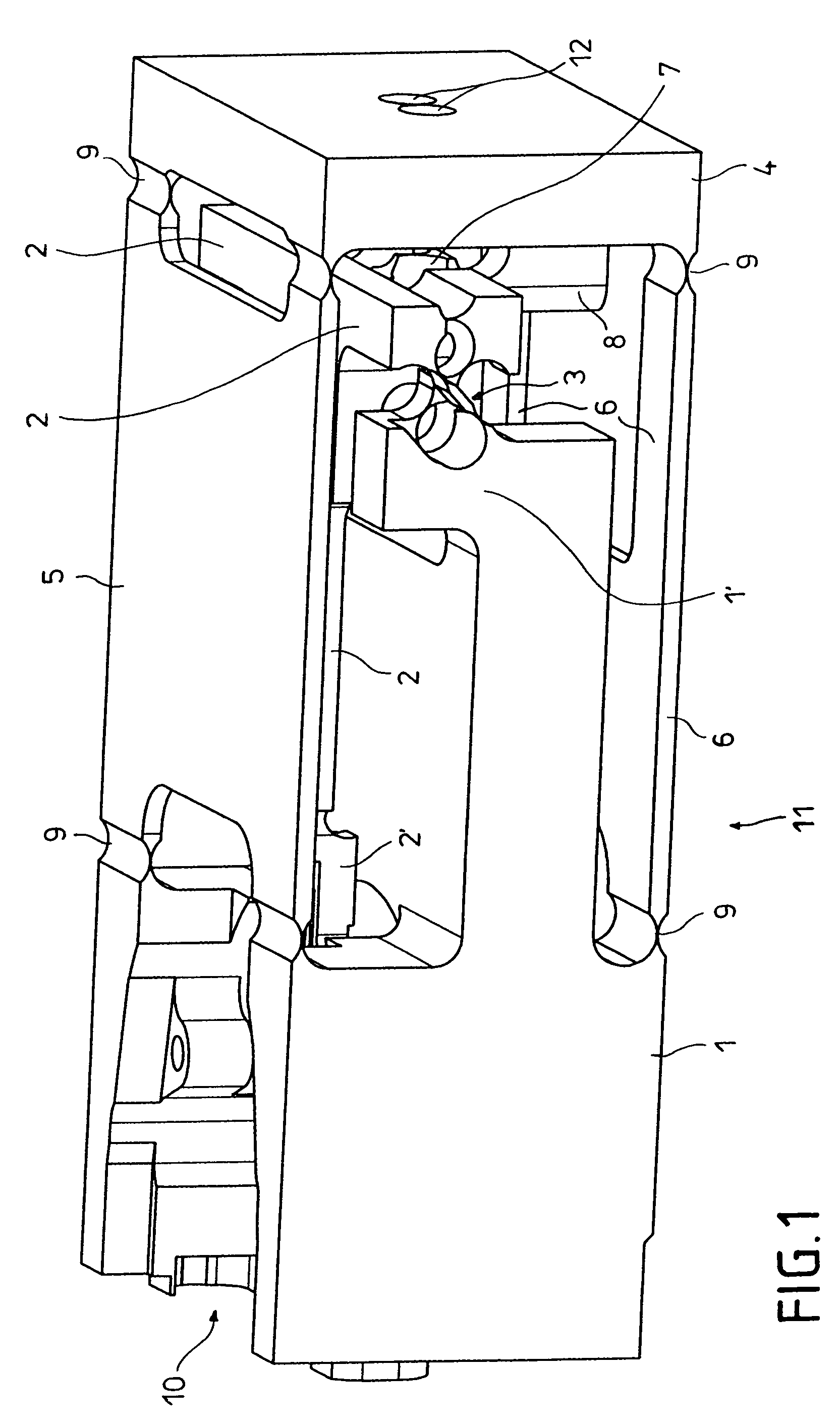
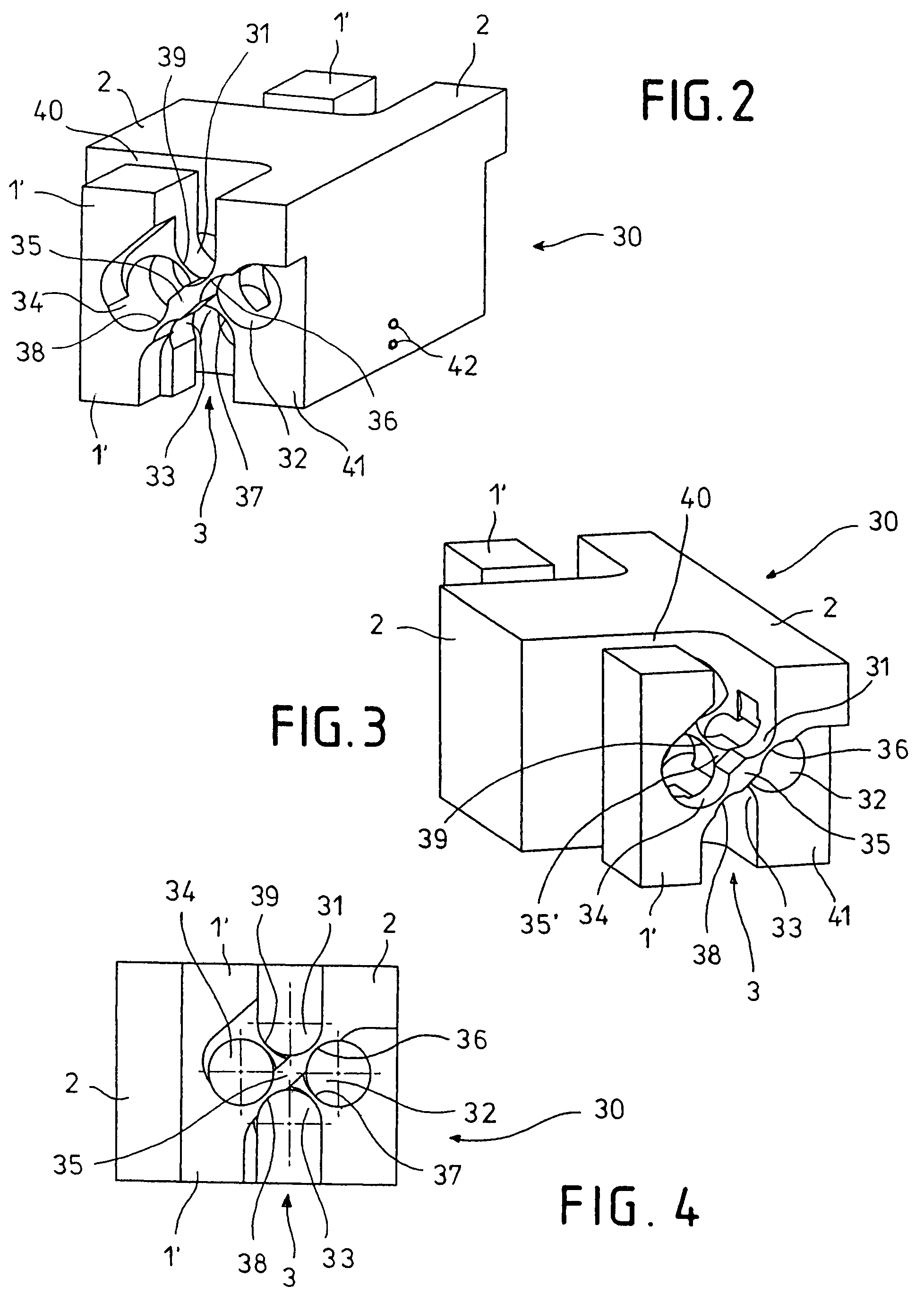
[0010]Because of the monolithic construction, the individual springs of the flexural pivot do not have to be screwed, welded or in some other way connected to the base region and the transmission lever. Rather, they are formed from the block by the four bores and the slots, so as to prevent from the outset the introduction of stresses during assembly.

Problems solved by technology

In that design, however, no flexural pivots are provided for mounting the transmission lever but rather individual vertical springs.
Furthermore with regard to transport safety of the weighing systems, individual springs are much more critical than cross-shaped springs, so that they often cannot replace flexural pivots.

Method used


Image

  • Weighing system of monolithic construction including flexural pivot
  • Weighing system of monolithic construction including flexural pivot
  • Weighing system of monolithic construction including flexural pivot

Examples


first embodiment

[0025]FIGS. 2 to 4 show the flexural pivot in a FIGS. 2 and 3 are perspective views from two different angles while FIG. 4 is a side elevation. The figures show that the flexural pivot 3 is essentially formed from the material block 30 by four horizontal bores 31, 32, 33 and 34 with the same diameter. In FIG. 4 the center points of these bores are suggested by thin coordinate axes. These center points are located in the corners of a square standing on one tip. The bore 31 is expanded upwardly to an opening in the region of the flexural pivot. The bore 33 is similarly expanded downwardly to an opening. Between the four bores initially remains a cross-shaped inner part 35 / 35′ that is connected to the rest of the block 30 by four thin connecting segments 36, 37, 38 and 39. In a next production step, the flexural pivot 3 is separated from the transmission lever 2 by a vertical slot 40 and divided into two partial areas by another vertical slot, whose rear boundary 41 is visible in FIGS...

fourth embodiment

[0034]FIGS. 8 to 10 show a The representation corresponds to that of FIGS. 2 to 4: FIGS. 8 and 9 are perspective views from two different angles. FIG. 10 is a side elevation. Parts that are the same as those depicted in FIGS. 2 to 4 are again identified by the same reference numbers and will not be re-explained here. In the embodiment shown in FIGS. 8 to 10, the center points of the bores 31 to 34 are not situated in the corners of a square but in the corners of a rectangle with unequal sides. This is best seen in FIG. 10: the distance between the bores 31 and 34 as well as 32 and 33 is smaller than the distance between the bores 31 and 32 as well as 34 and 33. The connecting segments 36 and 38 are therefore thicker than the connecting segments 37 and 39. The thinner connecting segments 37 and 39 act as linkages in the manner described above with reference to other embodiments. The thicker connecting segments 36 and 38 are clearly more stable, and the actual linkage between them is...


PUM


Abstract

A weighing system having a base region (1), a parallel-guided load receiver (4), at least one transmission lever (2) that is pivotably mounted on the base region via at least one flexural pivot (3), and a coupling element (7) that connects the load sensor to the short lever arm of the transmission lever. The flexural pivot (3), at least one part of the transmission lever (2), and at least one part of the base region (1′) are monolithically formed from a block. The flexural pivot (3) is separated from the rest of the block by four horizontal parallel bores (31, 32, 33, 34) that are adjacently arranged in an annular manner in such a way as to respectively leave a thin connecting segment (36, 37, 38 39) between adjacent bores, and by additional slots. In this way, a hysteresis-free flexural pivot can be created without the need for separate assembly components.

Description

[0001]This is a Continuation of International Application PCT / EP2006 / 000831, with an international filing date of Feb. 1, 2006, which was published under PCT Article 21(2) in German, and the disclosure of which is incorporated into this application by reference.FIELD AND BACKGROUND OF THE INVENTION[0002]The invention relates to a weighing system having a base region, a parallel-guided load receiver, at least one transmission lever that is pivotably mounted on the base region by means of at least one flexural pivot, and a coupling element that connects the load receiver to the short lever arm of the transmission lever.[0003]Weighing systems of this kind are conventional in the art and are described, for example, in German Utility Model DE-Gbm 81 35 182.[0004]A disadvantage of this known weighing system is that the complexity of assembly and calibration of the flexural pivot constructed of individual leaf springs is relatively high and securing the leaf springs to the transmission lev...

Claims


Application Information

Patent Timeline
Patent Type & Authority Patents(United States)
IPC IPC(8): G01G3/12G01G7/00
CPCG01G21/244
Inventor KUHLMANN, OTTOFLEISCHER, PETERHELMSEN, FRIEDRICHFEHLING, THOMAS
Owner SARTORIUS LAB INSTR GMBH & CO KG
Learn More