Method for optical chassis measurement

Active Publication Date: 2009-05-19
BEISSBARTH
View PDF13 Cites 17 Cited by
  • Summary
  • Abstract
  • Description
  • Claims
  • Application Information

AI Technical Summary

Benefits of technology

[0004]The object of the present invention is to provide a method for optical chassis measurement that

Problems solved by technology

This makes it unnecessary to affix and adapt measurement marks to the vehicle wheel and chassis while the measurement device, based on existing surface structures and using the above-mentioned techniques, reliably and unambiguously acquires the surfa

Method used


Image

  • Method for optical chassis measurement
  • Method for optical chassis measurement
  • Method for optical chassis measurement

Examples


Embodiment Construction

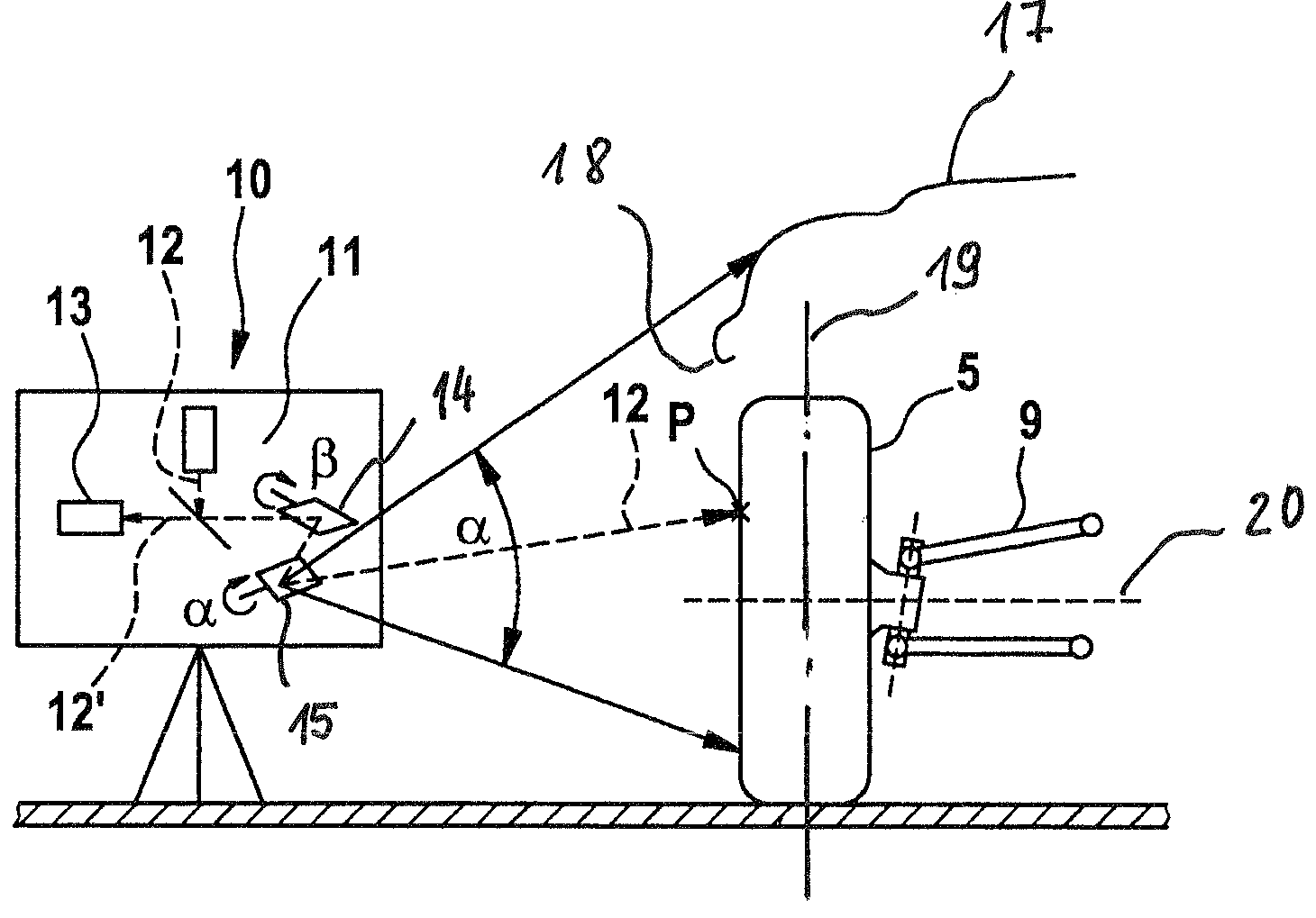
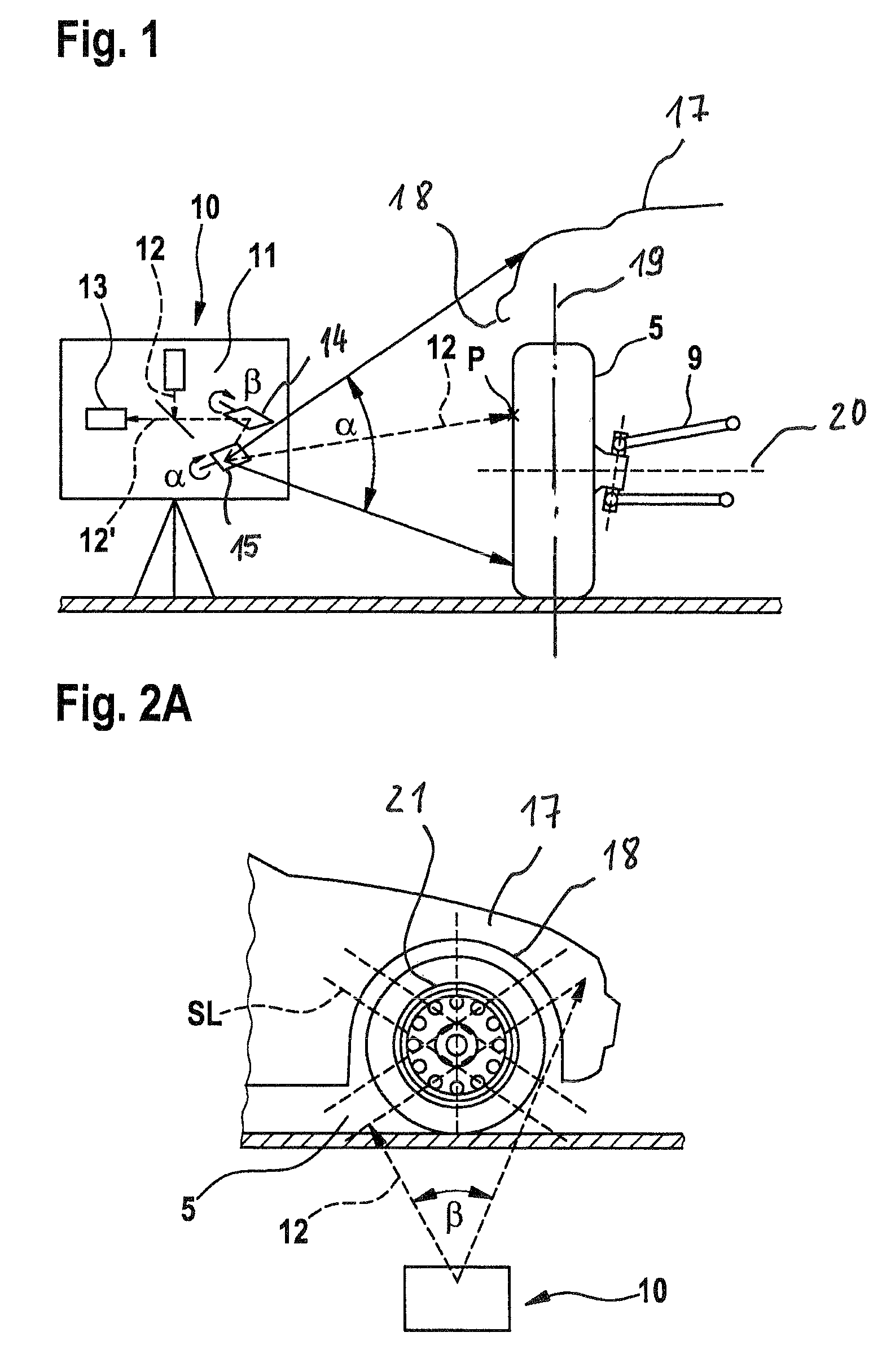
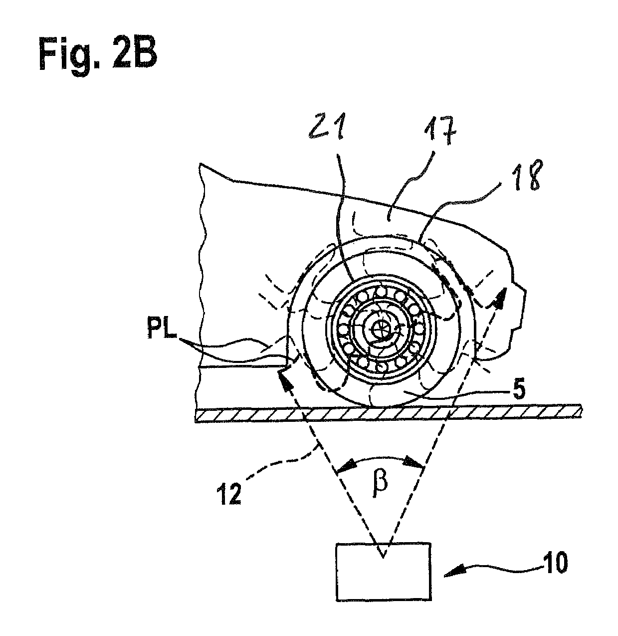
[0017]FIGS. 1, 2A, and 2B show a measuring instrument of a measuring device 10 situated to the side of a vehicle, in the region of a wheel 5. The measuring instrument includes a laser scanner 11, which emits a measurement beam 12 at defined deflection angles α, β, and a sensor system 13, which detects the reflected measurement beam 12′ as well as its travel time and phase difference. The measurement instrument is also connected to computers whose computing power is appropriate to the complexity of the measurement. The measuring device 10 is able to determine a variety of data, particularly with regard to a wheel suspension 9.

[0018]The measuring instrument scans surface points P by tilting and panning the laser beam or measurement beam 12 in accordance with a horizontal angle β and a vertical angle α and determines the distance between the measuring instrument and the surface points P that yield the related surface structure. Based on intersecting lines SL of the scanning laser beam,...


PUM


Abstract

The invention relates to a method for optically measuring a chassis at a testing station. According to said method, radiation that is reflected by a surface structure of a vehicle, comprising at least one wheel (5) and a surrounding bodywork section, is detected by a measuring device with the aid of appropriate sensors, and at least the wheel plane and the wheel center point are determined by an evaluation of the positional data obtained by means of the detected radiation. To achieve a reliable, precise measurement of the chassis in a simple operation, the surface structure of at least the vehicle bodywork section and at least the wheel is scanned, over its entire surface or at least by any two lines that record both the wheel and the bodywork, using a laser beam (12) that is emitted by the measuring device (10), and at least two surface profiles are obtained from the scanned surface structure as characteristic structures.

Description

CROSS-REFERENCE TO RELATED APPLICATION[0001]The invention described and claimed herein below is also described in German Patent Application DE 10 2005 063 082.0 filed on Dec. 29, 2005. This German Patent Application, whose subject matter is incorporated here by reference, provides the basis for a claim of priority of invention under 35U.S.C. 119(a)-(d).BACKGROUND OF THE INVENTION[0002]The invention relates to a method for optical chassis measurement at a testing station, in which radiation reflected against a surface structure of a vehicle, including at least one wheel and a chassis opening surrounding it, is detected by a measuring device by means of a corresponding sensor system and, through evaluation of position data acquired from the detected radiation, at least the wheel plane and the wheel center point are determined.[0003]A method for optical chassis measurement of this kind has been disclosed by DE 197 57 763 A1 and also in similar fashion by FP 1 042 643 B1. In these known...

Claims


Application Information

Patent Timeline
IPC IPC(8): G01B11/26
CPCG01B11/2755G01B2210/20G01B2210/28
Inventor UFFENKAMP, VOLKERNOBIS, GUENTER
Owner BEISSBARTH
Why Eureka
Try Eureka