Video encoding/decoding apparatus and method for color image

a video encoding and color image technology, applied in the field of video encoding/decoding apparatus for color images, can solve the problems of low encoding efficiency, inconvenient video compression method for applications requiring high-quality image restoration, and insufficient encoding characteristics of y-cb-cr image and r-g-b image, so as to improve the encoding/decoding efficiency of an r-g-b image

Inactive Publication Date: 2009-05-19
SAMSUNG ELECTRONICS CO LTD
View PDF14 Cites 58 Cited by
  • Summary
  • Abstract
  • Description
  • Claims
  • Application Information

AI Technical Summary

Benefits of technology

[0009]The present invention provides a video encoding / decoding apparatus and method to enhance the encoding / decoding efficiency of an R-G-B image using inter-plane prediction.
[0011]The present invention also provides a deblocking filter to reduce block efficiency effectively according to color information and resolution information upon video encoding / decoding, and a deblocking filtering method therefor.
[0014]According to another aspect of the present invention, a video decoding apparatus comprises: a first restoration unit performing a predetermined operation for an encoded image and generating a first prediction residue image of the encoded image; an image information detection unit determining whether the encoded image is an R-G-B image or a Y-Cb-Cr image and whether a color component of the encoded image is a reference color component of the R-G-B image; a second restoration unit generating a second prediction residue image of the encoded image on a basis of the reference color component if the encoded image is the R-G-B image and the color component of the encoded image is not the reference color component; a deblocking filter unit reducing a block effect of a decoded image of an encoded image restored on a basis of the first prediction residue image and the second prediction residue image.
[0015]According to another aspect of the present invention, a video decoding method comprises: performing a predetermined operation of an encoded image and generating a first prediction residue image of the encoded image; determining whether the encoded image is an R-G-B image or a Y-Cb-Cr image and whether a color component of the encoded image is a reference color component of the R-G-B image; generating a second prediction residue image of the encoded image on a basis of the reference color component if the encoded image is the R-G-B image and the color component of the encoded image is not the reference color component; and reducing a block effect of a decoded image of an encoded image restored on a basis of the first prediction residue image and the second prediction residue image.
[0020]According to another aspect of the present invention, a deblocking filter apparatus, which is included in a video decoder or video encoder, comprises: an image information detector detecting color information of an image; a deblocking filter selector selecting a length of a deblocking filter tap for reducing block effect of the image on a basis of the color information; a filtering unit filtering the image using a deblocking filter with the selected tap length.
[0021]According to another aspect of the present invention, a deblocking filter selection method, which is performed by a decoder or encoder, comprises: detecting color information of an image; selecting a length of a deblocking filer for reducing block effect of the image on a basis of the color information; and filtering the image using a deblocking filter with the selected length.

Problems solved by technology

However, the conventional video compression method is not suitable for applications requiring high-quality image restoration because energy loss is generated due to subsampling of the Cb and Cr components and the quality loss of the corresponding image which is generated when R-G-B components are converted into Y-Cb-Cr components.
However, the conventional video compression method encodes the R-G-B components using a conventional Y-Cb-Cr encoder without utilizing characteristics existing in the R-G-B color components different from those of Y-Cb-Cr components.
However, since an R-G-B component and a Y-Cb-Cr component have different image characteristics, encoding efficiency is very low if the R-G-B component is encoded by the conventional Y-Cb-Cr encoder.
As such, the conventional video compression method has not correctly reflected characteristics of the R-G-B image and the Y-Cb-Cr image with respect to encoding.
Also, the conventional video compression method has not reflected the change of the frequency characteristic according to the size of an image when encoding.

Method used


Image

  • Video encoding/decoding apparatus and method for color image
  • Video encoding/decoding apparatus and method for color image
  • Video encoding/decoding apparatus and method for color image

Examples


Embodiment Construction

[0040]Reference will now be made in detail to the embodiments of the present invention, examples of which are illustrated in the accompanying drawings, wherein like reference numerals refer to the like elements throughout. The embodiments are described below to explain the present invention by referring to the figures.

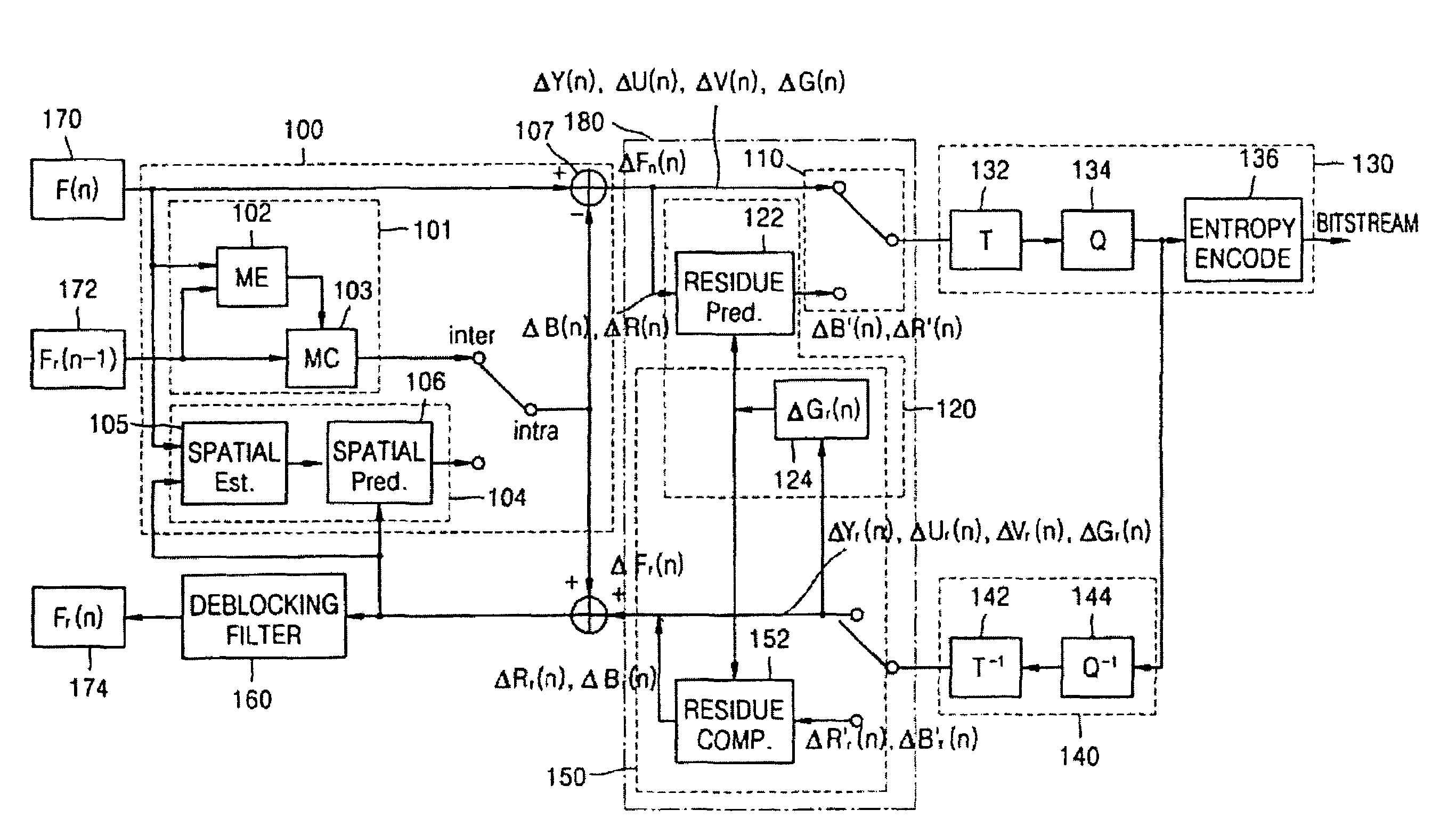
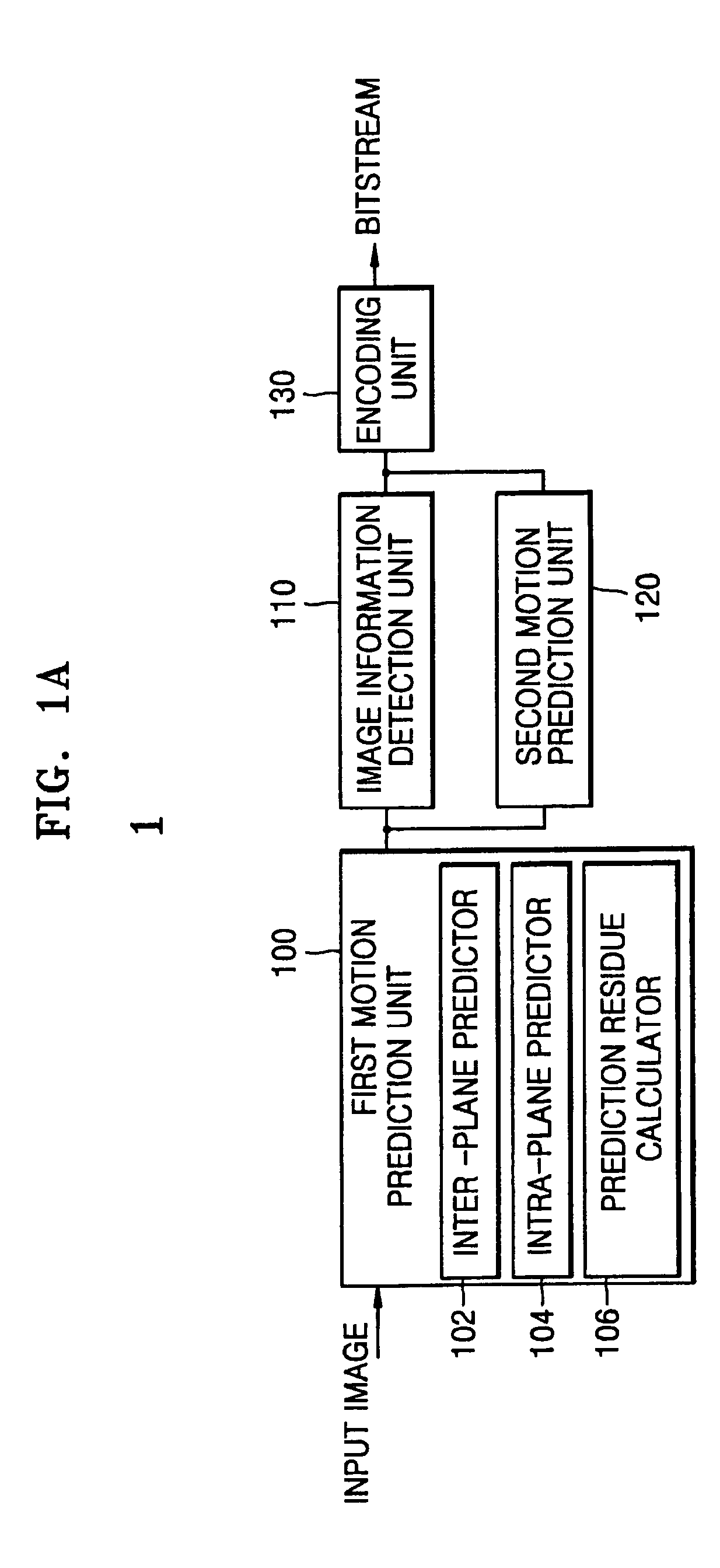
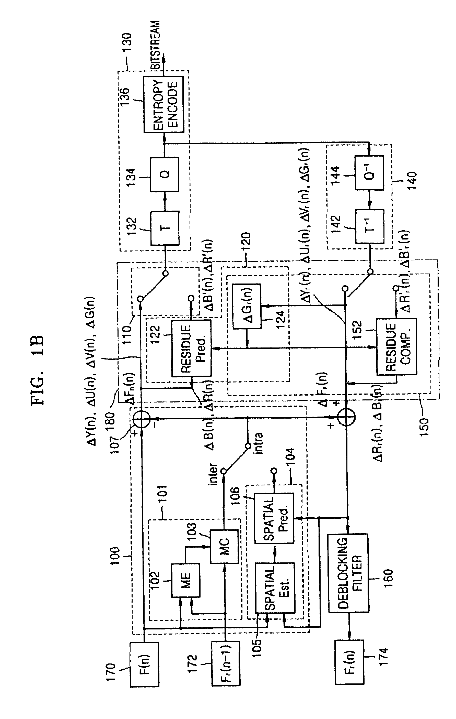
[0041]FIG. 1A is a block diagram showing a structure of a video encoding apparatus according to an embodiment of the present invention. Referring to FIG. 1A, the video encoding apparatus includes a first motion prediction unit 100, an image information detection unit 110, a second motion prediction unit 120, and an encoding unit 130. The first motion prediction unit 100 includes an inter-plane predictor 102, an intra-plane predictor 104, and a prediction residue calculator 106.

[0042]The inter-plane predictor 102 and intra-plane predictor 104 of the first motion prediction unit 100 perform motion prediction of an input image on a basis of temporally and spatially adjace...


PUM


Abstract

A video encoding / decoding apparatus and method for color images include a first motion prediction unit that generates a first prediction residue image of an input image on a basis of a first motion prediction result of the input image. An image information detection unit sets a predetermined color component of an R-G-B image to a reference color component and determines whether the input image is a Y-Cb-Cr image or an R-G-B image and whether a color component is the reference color component. A second motion prediction unit performs motion prediction for the first prediction residue image and generates a second prediction residue image if the input image is the R-G-B image and the color component of the input image is not the reference color component.

Description

CROSS-REFERENCE TO RELATED APPLICATIONS[0001]This application claims the priority of Korean Patent Application No. 2003-48666, filed on Jul. 16, 2003, in the Korean Intellectual Property Office, the disclosure of which is incorporated herein in its entirety by reference.BACKGROUND OF THE INVENTION[0002]1. Field of the Invention[0003]The present invention relates to a video encoding / decoding apparatus for color images, and more particularly, to an apparatus and method for performing optimal encoding / decoding on a basis of color information and resolution information of color images.[0004]2. Description of the Related Art[0005]A conventional video compression method converts an image format such as an R-G-B image into an image format such as a Y-Cb-Cr image suitable to compression, to obtain a high compression rate. Also, the conventional video compression method reduces chroma (Cb, Cr) components to ¼ of their original sizes and encodes the Cb and Cr components to enhance compression...

Claims


Application Information

Patent Timeline
Patent Type & Authority Patents(United States)
IPC IPC(8): H04N7/12H04N11/04H04N7/24H04N19/117H04N19/136H04N19/176H04N19/186H04N19/196H04N19/50H04N19/503H04N19/51H04N19/523H04N19/59H04N19/593H04N19/60H04N19/61H04N19/625H04N19/80H04N19/86H04N19/91
CPCH04N19/105H04N19/176H04N19/61H04N19/593H04N19/86H04N19/186H04N19/527H04N19/523H04N19/117H04N19/51
Inventor CHO, DAE-SUNGKIM, HYUN MUNKIM, WOO-SHIK
Owner SAMSUNG ELECTRONICS CO LTD
Why Eureka
Try Eureka