
Clock adjustment apparatus and method thereof

a clock signal and clock technology, applied in the direction of pulse technique, transmission monitoring, instruments, etc., can solve the problems of time lag between a clock signal and a data signal, system is not available for high-speed transmission, etc., and achieve the effect of improving the time lag

Active Publication Date: 2009-05-19
FUJITSU LTD
View PDF25 Cites 2 Cited by
  • Summary
  • Abstract
  • Description
  • Claims
  • Application Information

AI Technical Summary

Benefits of technology

This solution effectively reduces time lags caused by variations and fluctuations, allowing for improved synchronization of clock and data signals, even in high-speed and multi-bit data transmissions, without requiring changes to the transmission apparatus and maintaining a digital circuit scale.

Problems solved by technology

However, there is the following problem in the above-mentioned conventional transmission systems.
In the synchronous system (a), the clock signal and data signal are relatively lagged by both the piece-to-piece variations and a temperature / voltage fluctuation so that this system is not available for high speed transmission.
In the source synchronous system (b), the tolerance to the piece-to-piece variations and a temperature / voltage fluctuation are improved, but the time lag between a clock signal and a data signal becomes a problem when they are used in ultrahigh speed transmission.

Method used


Image

  • Clock adjustment apparatus and method thereof
  • Clock adjustment apparatus and method thereof
  • Clock adjustment apparatus and method thereof

Examples


Embodiment Construction

[0040]The following is the detailed explanation of the preferred embodiments of the present invention in reference to the drawings.

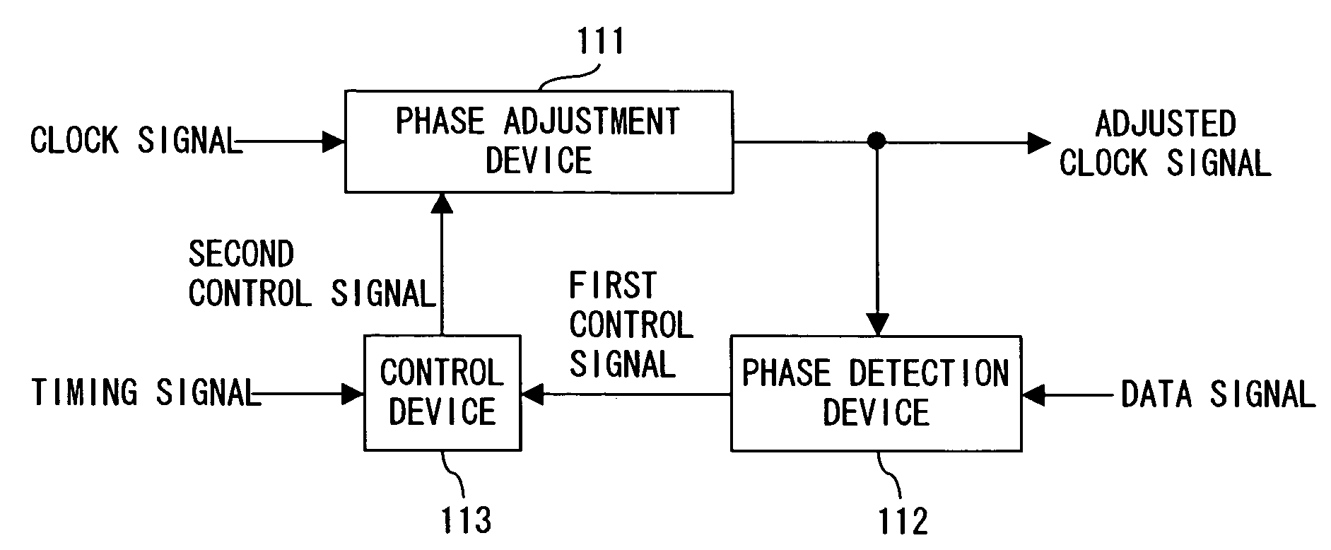
[0041]FIG. 2A shows the principle of a clock adjustment apparatus of the present invention. A clock adjustment apparatus of FIG. 2A comprises a phase adjustment device 111, a phase detection device 112 and a control device 113.

[0042]The phase adjustment device 111 delays an inputted clock signal and adjusts a phase of the delayed clock signal, thereby outputting the adjusted clock signal. The phase detection device 112 detects a phase relation between an inputted data signal and the adjusted clock signal and outputs a first control signal showing this phase relation. The control device 113 determines whether a delay amount of the phase adjustment device 111 is increased or decreased in accordance with the first control signal and generates a second control signal for increasing or decreasing the delay amount in accordance with an inputted timing signal, ...


PUM


Abstract

A clock adjustment apparatus delays a clock signal and adjusts a phase of the signal, thereby increasing or decreasing a delay amount of the clock signal in accordance with a phase relation between a data signal and an adjusted clock signal. The adjusted clock signal is used for receiving the data signal.

Description

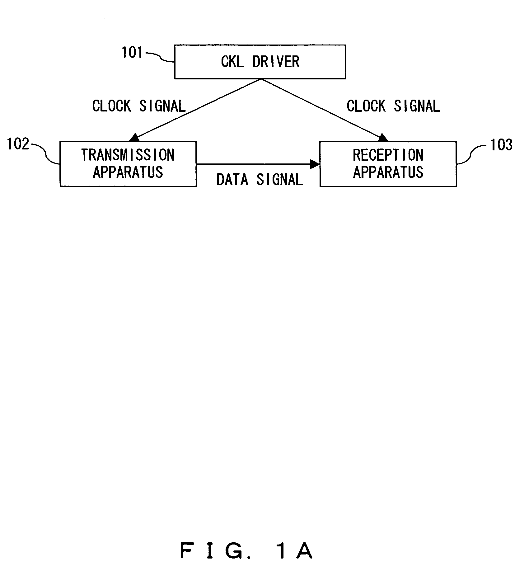
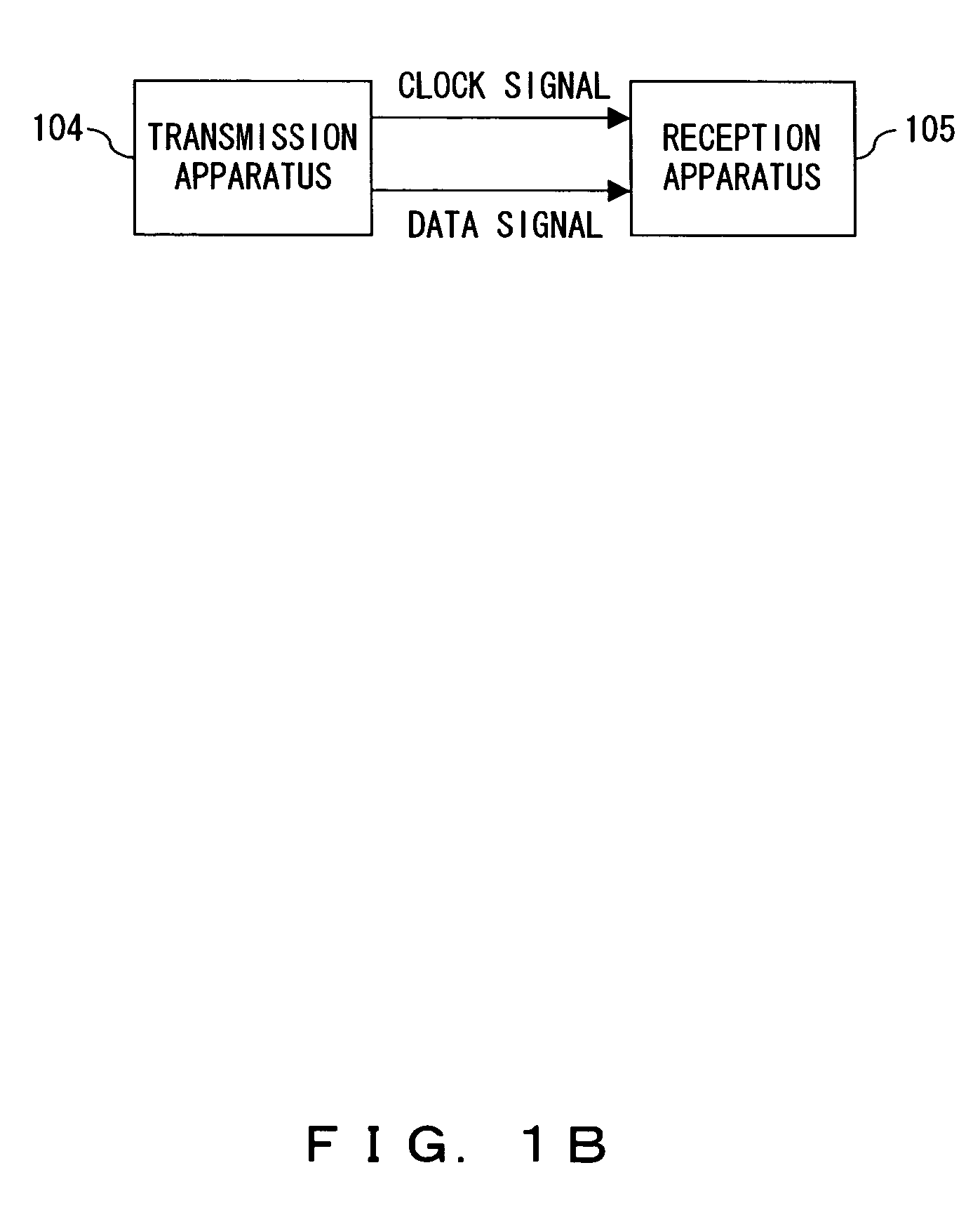
BACKGROUND OF THE INVENTION[0001]1. Field of the Invention[0002]The present invention relates to a signal transmission and reception circuit to be used for high speed digital transmission using a bus etc. inside a computer and specifically it relates to an apparatus and a method of adjusting the clock of a reception apparatus.[0003]2. Description of the Related Art[0004]A conventional transmission method of synchronizing clock signals between a transmission apparatus and a reception apparatus includes mainly following two methods which are performed in a signal transmission and reception processing between the processor LSI (Large Scale Integration) circuit and the chip set LSI circuit of a computer.(a) Synchronous system[0005]As shown in FIG. 1A, clock signals are respectively distributed to a transmission apparatus 102 and a reception apparatus 103 as a strobe signal from a clock driver (CLK driver) 101 and data signals are transferred between these apparatuses.(b) Source Synchron...

Claims


Application Information

Patent Timeline
Patent Type & Authority Patents(United States)
IPC IPC(8): H04L7/00G06F1/00G06F13/42H03K11/00H03K9/00H04B3/46G06F15/16H03L7/081H03L7/091H03L7/093H04L7/02H04L7/033
CPCH03L7/0814H03L7/091H03L7/093G06F15/16
Inventor YAMADA, JUN
Owner FUJITSU LTD
Learn More