
Power cable tension control device

a technology of tension control device and power cable, which is applied in the direction of insulated conductors, coupling device connections, cables, etc., can solve the problems of inoperable power, inability to operate, and high cost of repair or replacement of ac power ports, so as to prolong the life of computer ac power cables and computer ac power ports, and reduce tension or force

Active Publication Date: 2009-05-26
CROSSMAN II RALPH B +1
View PDF14 Cites 8 Cited by
  • Summary
  • Abstract
  • Description
  • Claims
  • Application Information

AI Technical Summary

Benefits of technology

"The present invention is a device that extends the life of computer AC power cables and ports by reducing tension or force applied to them during use. It can be used with any computer, but is particularly useful for mobile computers like laptops and palmtop computers. The device includes an adapter that connects to a computer port and a cable retaining structure that receives a power cable. It also includes a connector and a female component that can reversibly interlock with a male component, allowing for easy adjustment and secure retention of the power cable. The device can be adjusted along multiple planes or directions, and can also include a clamp to further secure the power cable. Overall, the invention provides a simple and effective solution to extend the life of computer AC power cables and ports."

Problems solved by technology

However, when the computer is moved or adjusted, strain on the power cable or computer power port may occur.
Continual or routine strain leads to an inoperable power cable or computer AC power port.
Damaged AC power cables must be repaired or replaced.
When the computer AC power port is inoperable the laptop computer can only function on its battery power, repair or replacement of the AC power port can be quite costly.

Method used


Image

  • Power cable tension control device
  • Power cable tension control device
  • Power cable tension control device

Examples


Embodiment Construction

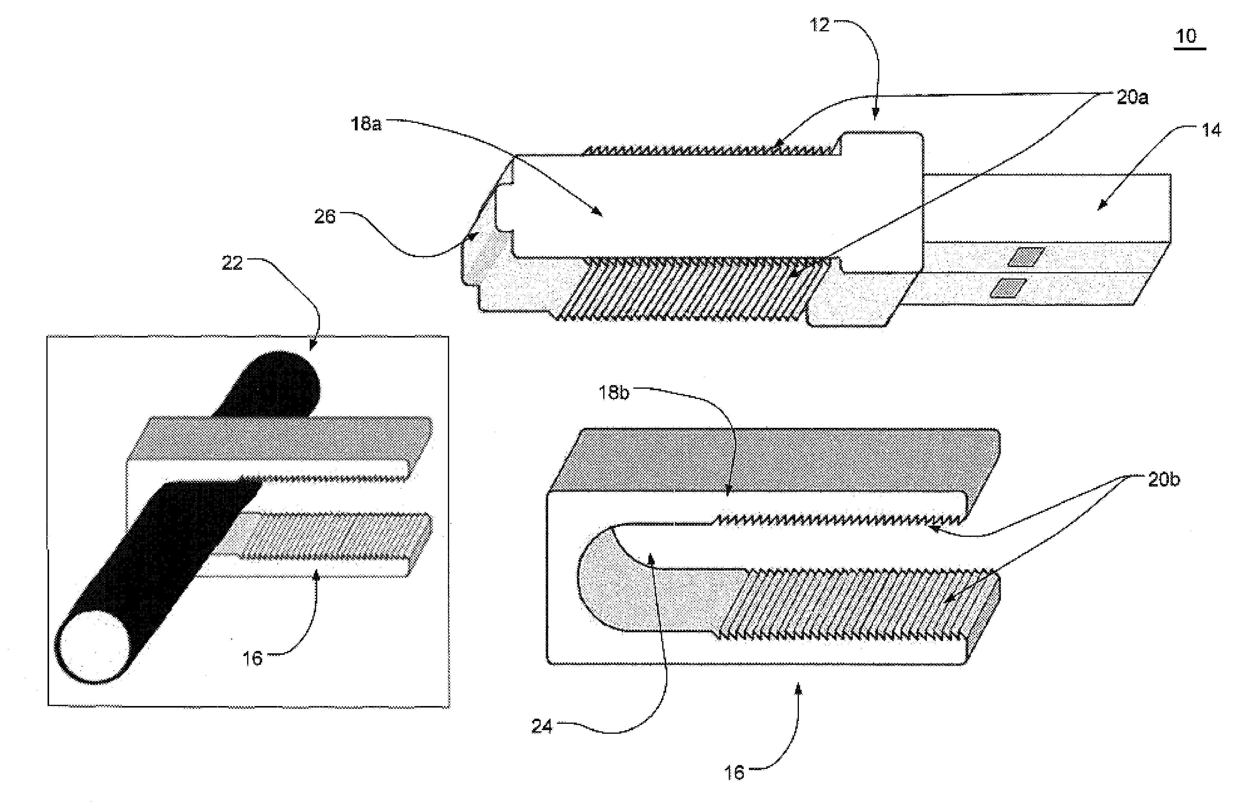
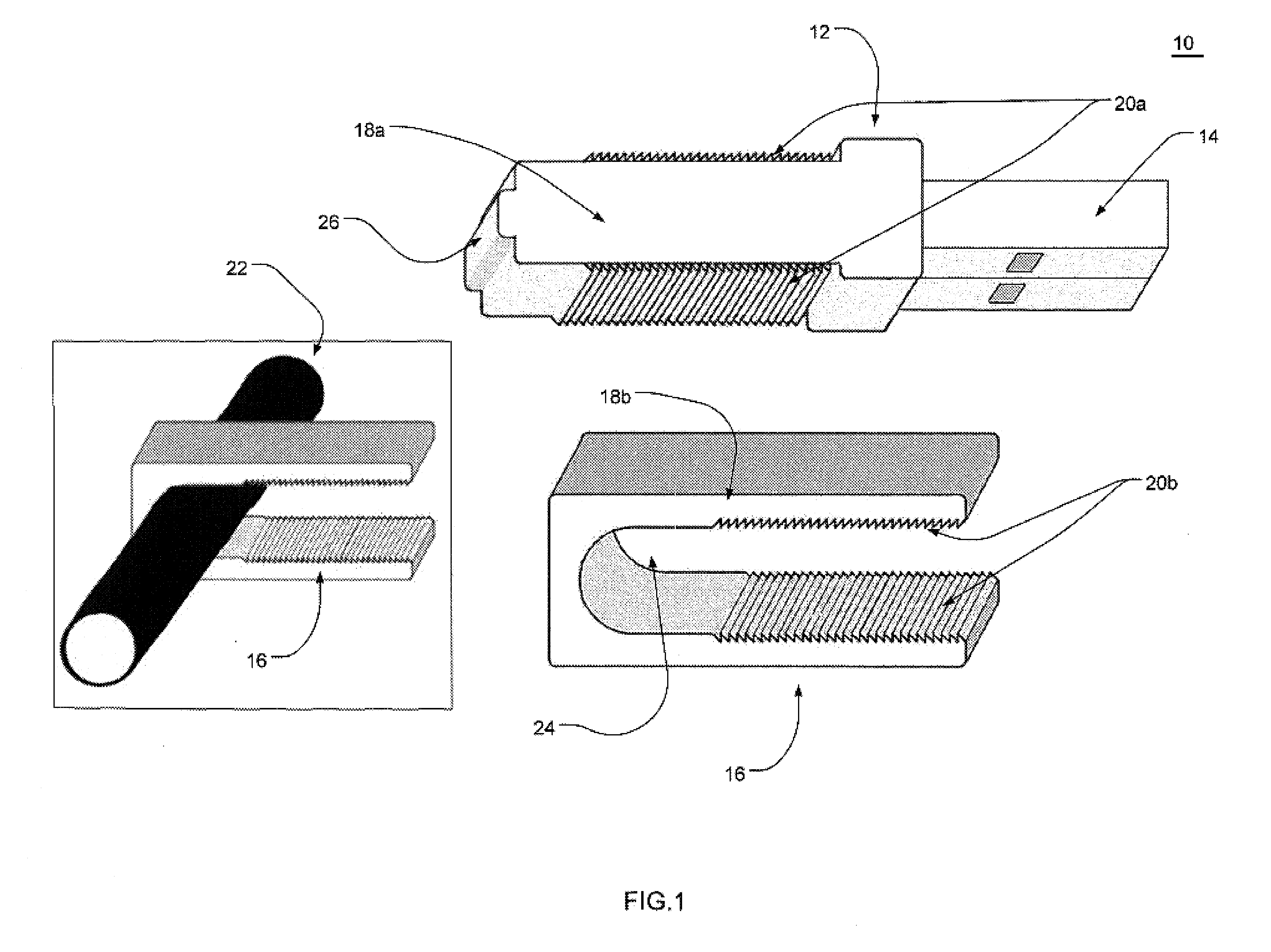
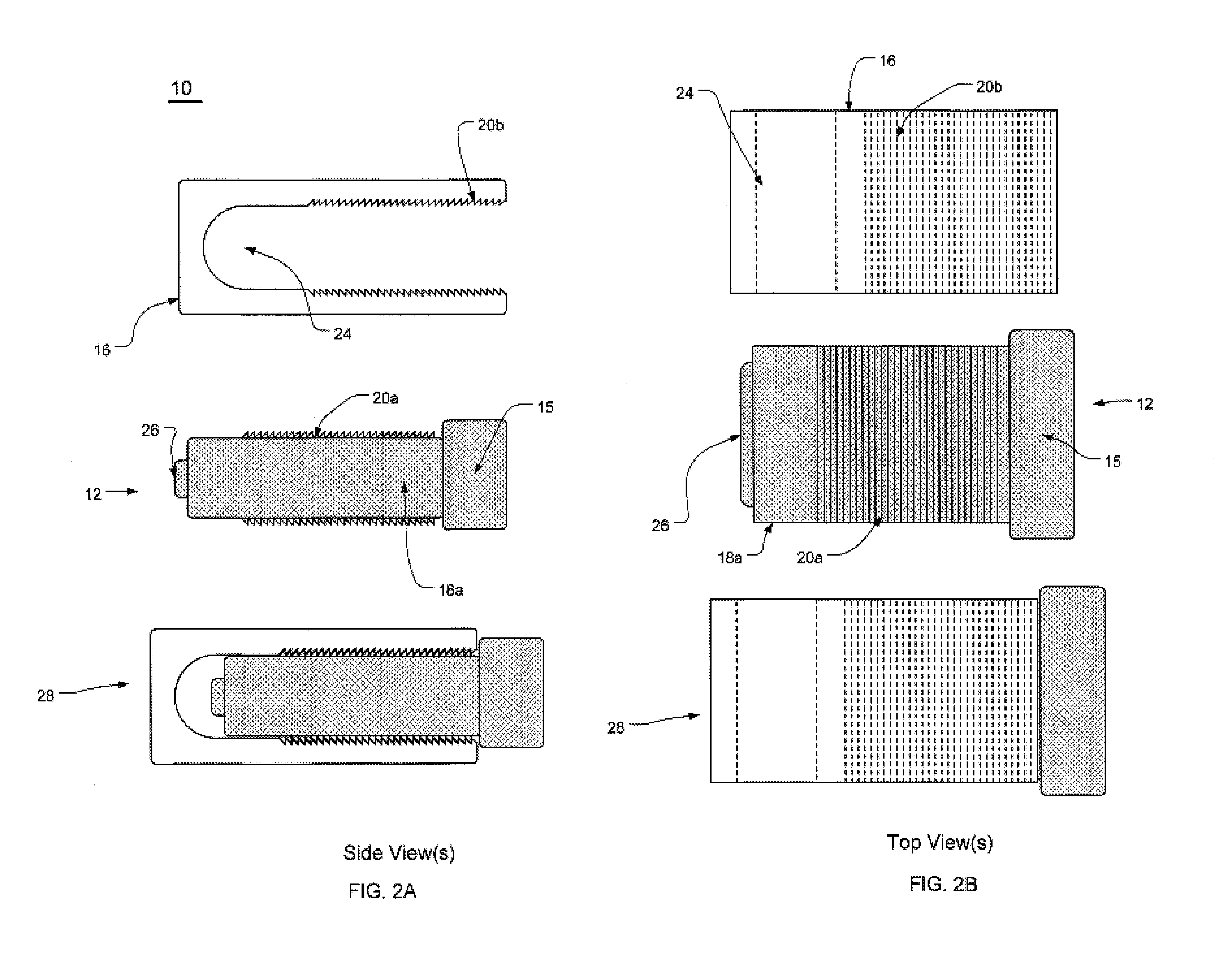
[0018]The present invention provides a power cable tension control device 10 for reducing the strain placed on a power cable 22 or a computer port, which extends the life of the power cable 22 or computer port under typical use. The term “power cable” as used herein refers to any cable that delivers an electrical signal to a computer such as but limited to an AC power cable, an Ethernet cable, a phone line cable, a speaker cable, a mouse cable, a keyboard cable and the like. The device 10 may be used whenever an available computer port exists.

[0019]More specifically, the present invention includes a device 10 having at one end an adapter 12 capable of insertion into a computer port and at the opposing end a cable retaining structure 16 for retaining a power cable 22, such as an AC power cable. The adapter 12 does not electrically communicate with the retained power cable 22 and therefore does not act as a conduit through which the power cable 22 electrically communicates with the co...


PUM


Abstract

The present invention includes a power cable tension control device having at one end an adapter capable of insertion into a computer port and at the opposing end a cable retaining structure for retaining a power cable, such as an AC power cable. The adapter does not electrically communicate with the retained power cable and therefore does not act as a conduit through which the power cable electrically communicates with the computer. The computer cable communicates with the computer using a port away from the adapter. Thus, the present invention provides a device that further anchors the power cable to the computer thereby reducing strain on the plug region of the power cable or the computer port, which prolongs the life of the power cable or computer port.

Description

TECHNICAL FIELD[0001]The present invention relates to devices for securing electronic cables and more specifically to a power cable tension control device that uses an available computer port to further anchor the AC power cable.BACKGROUND OF THE INVENTION[0002]Computers are routinely used throughout the world. The emergence of laptop and palmtop computers encourages our development as an increasingly mobile computer society. However even laptop and palmtop computers require a power cable or at least temporary connectivity through some form of an AC power cable. These power cables provide a means to supply electrical current to the laptop computer and to charge the battery typical of all laptop computers. Power cables typically include a jack at one end for insertion into a corresponding power port on the computer.[0003]Mobile computer users frequently place the computer on the lap and plug in the AC power cable. However, when the computer is moved or adjusted, strain on the power c...

Claims


Application Information

Patent Timeline
Patent Type & Authority Patents(United States)
IPC IPC(8): H01R13/62
CPCG06F1/1613H01R13/5804H02G15/007H01R2201/06
Inventor CROSSMAN, II, RALPH B.CROSSMAN, LAUREL A.
Owner CROSSMAN II RALPH B
Learn More