Intravascular dilatation infusion catheter

a technology of infusion catheter and intravascular dilatation, which is applied in the field of medical devices, can solve the problems that current catheter systems do not provide both a mechanism and a mechanism adequately

Active Publication Date: 2009-05-26
STRYKER CORP +1
View PDF42 Cites 37 Cited by
  • Summary
  • Abstract
  • Description
  • Claims
  • Application Information

AI Technical Summary

Benefits of technology

[0018]In at least one embodiment, coolant ports are configured to allow the infusate to exit the balloon under pressure but prevent or restrict the flow of bodily fluids into the balloon during deflation.
[0021]In some embodiments a medical device comprises a balloon catheter wherein the inner shaft distal of the balloon is provided with at least one coolant exit port. The guidewire lumen defined by the inner shaft is in fluid communication with the balloon to permit the inflation fluid / coolant to flow from the balloon, through the inner shaft and into the guidewire lumen, and out the distal coolant exit port or ports. In at least one embodiment the catheter comprises a fluid static valve to control and / or prevent pressure loss of the coolant out the proximal end of the guidewire lumen.
[0024]In at least one embodiment the catheter is provided with one or more valve mechanisms to control the direction of the coolant flow through the port(s). In at least one embodiment the valve mechanism is positioned inside the guidewire lumen to allow coolant to flow outward from the catheter but prevents backflow of fluid during deflation of the balloon.
[0025]In at least one embodiment the catheter avoids the use of the traditional inner shaft and outer shaft configuration by mounting the balloon directly to a single shaft which defines a dual inflation / guidewire lumen. The shaft comprises one or more fluid static valves to prevent fluid and pressure loss out the proximal and / or distal ends of the catheter.

Problems solved by technology

However current catheter systems do not adequately provide both a mechanism for establishing re-profusion and providing a cooling effect within the desired window.

Method used


Image

  • Intravascular dilatation infusion catheter
  • Intravascular dilatation infusion catheter
  • Intravascular dilatation infusion catheter

Examples


Embodiment Construction

[0042]While this invention may be embodied in many different forms, there are described in detail herein specific preferred embodiments of the invention. This description is an exemplification of the principles of the invention and is not intended to limit the invention to the particular embodiments illustrated.

[0043]For the purposes of this disclosure, like reference numerals in the figures shall refer to like features unless otherwise indicated.

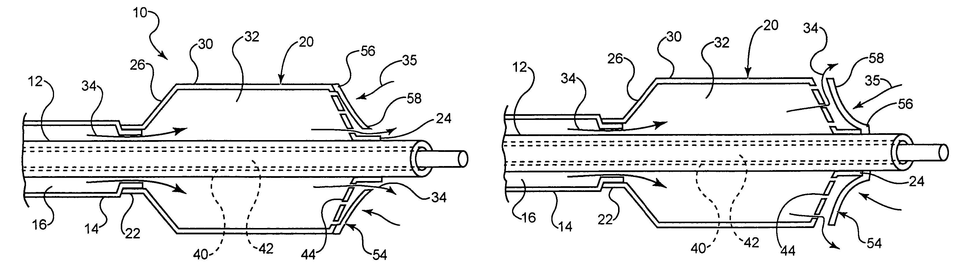
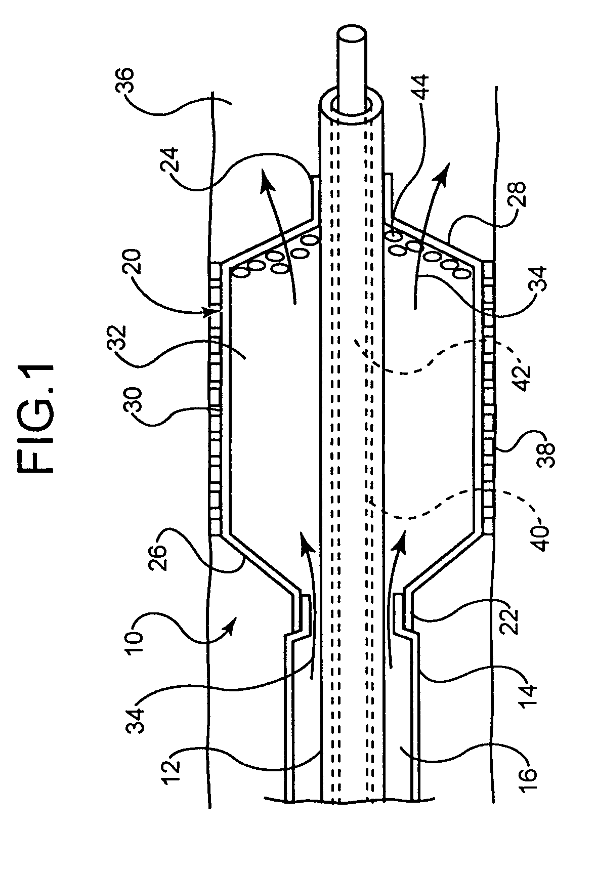
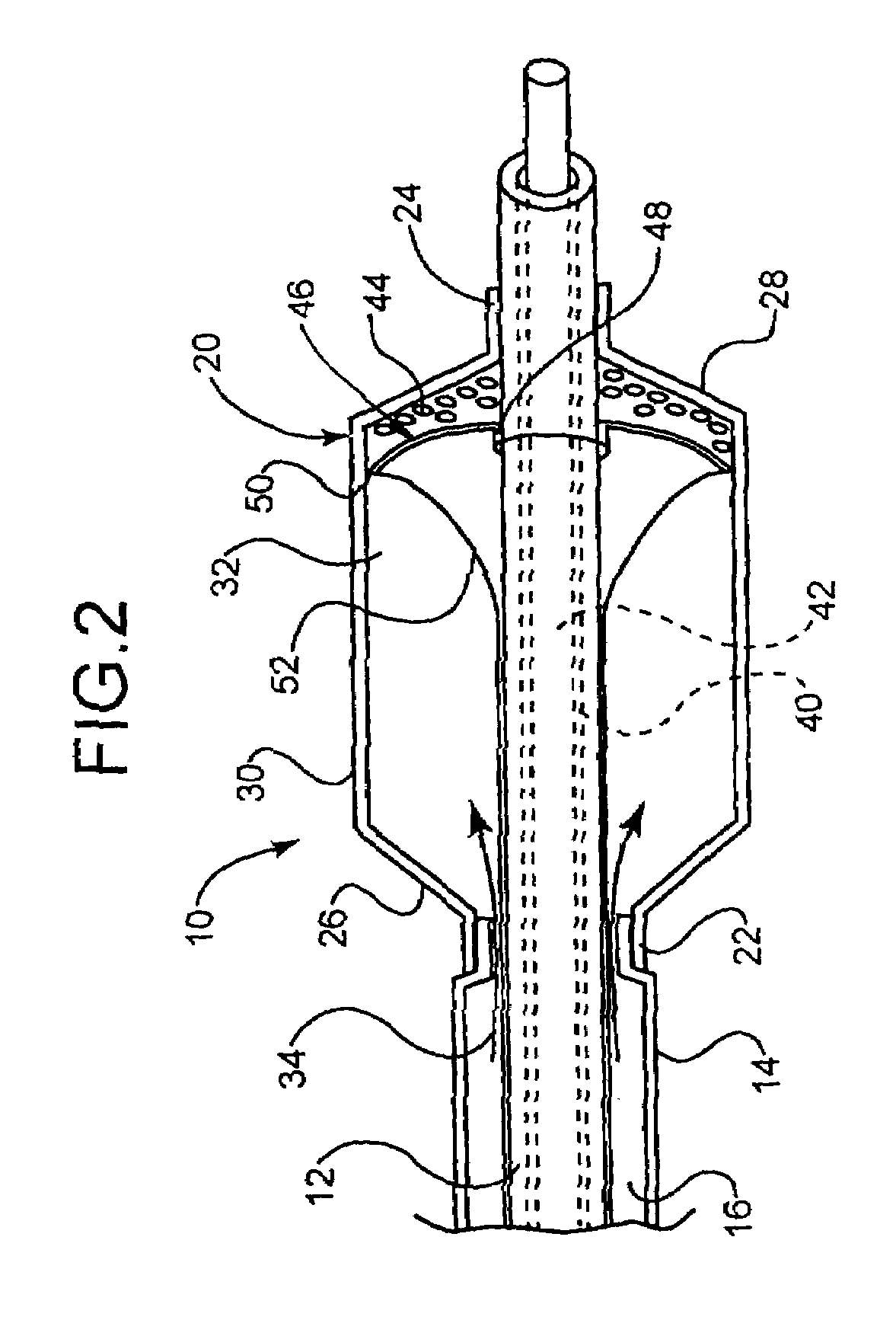
[0044]In at least one embodiment, an example of which is shown in FIG. 1, the invention is directed to a medical device comprising a catheter 10. The catheter 10 comprises an inner shaft 12 and outer shaft 14 and a balloon 20. The outer shaft 14 is disposed about a portion of the inner shaft 12. The radially adjacent portions of the shafts 12 and 14 define a lumen 16 therebetween.

[0045]The balloon 20 includes a proximal waist 22, a distal waist 24, a proximal cone 26, a distal cone 28 and a working or body portion 30 therebetween. When moun...


PUM


Abstract

A medical device comprises a catheter having at least one catheter shaft, which defines an inflation lumen for transport of an inflation fluid therethrough. The inflation fluid comprises a coolant. An expandable balloon, which has a proximal cone, distal cone, and a body region therebetween, is engaged to a distal region of the at least one catheter shaft. The balloon interior is in fluid communication with the inflation lumen. A portion of the catheter distal of the balloon body defines at least one port that is in fluid communication with the inflation lumen and the balloon interior.

Description

CROSS-REFERENCE TO RELATED APPLICATIONS[0001]Not ApplicableSTATEMENT REGARDING FEDERALLY SPONSORED RESEARCH[0002]Not ApplicableBACKGROUND OF THE INVENTION[0003]1. Field of the Invention[0004]This invention relates to medical devices such as catheters and catheter assemblies for use in medical procedures. More specifically, this invention relates to catheter systems, such as the kind used in percutaneous transluminal coronary angioplasty (PTCA) procedures, as well as the kind used in cryoplasty and / or cooling procedures.[0005]2. Description of the Related Art[0006]Percutaneous transluminal coronary angioplasty (PTCA) is a procedure which is well established for the treatment of blockages, lesions, stenosis, thrombus, etc. present in body lumens such as the coronary arteries and / or other vessels.[0007]A widely used form of percutaneous coronary angioplasty makes use of a dilatation balloon catheter which is introduced into and advanced through a lumen or body vessel until the distal e...

Claims


Application Information

Patent Timeline
Patent Type & Authority Patents(United States)
IPC IPC(8): A61M29/00A61F2/958A61M29/02A61M31/00
CPCA61M25/10A61M25/104A61M2025/105A61M2025/1093
Inventor WILLARD, MARTIN R.
Owner STRYKER CORP
Why Eureka
Try Eureka