Method for fabricating structure of thin film transistor array
a thin film transistor and array technology, applied in the direction of basic electric elements, electrical equipment, semiconductor devices, etc., can solve the problems of increasing fabrication costs, reducing fabrication costs, and more expensive masks, so as to reduce fabrication costs and simplify the process
- Summary
- Abstract
- Description
- Claims
- Application Information
AI Technical Summary
Benefits of technology
Problems solved by technology
Method used
Image
Examples
first embodiment
The First Embodiment
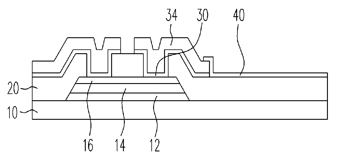
[0033]FIG. 3, FIGS. 4A to 4D, and FIG. 5 illustrate the first embodiment of the present invention. FIG. 3 is a cross-sectional view of the TFT fabricated using the fabricating method according to the first embodiment. FIGS. 4A to 4D are schematic views illustrating the process steps of fabricating method a TFT array according to the first embodiment of the present invention, in which the cross-sectional views shown at the left of each figure indicate the fabrication step, while the schematic views shown at the right side of each figure indicate the design of the display array. The left part of FIG. 5 is the schematic cross-sectional view of the gate pad or the gate line wiring area of the TFT in FIG. 3.
[0034]First, referring to FIG. 4A, a gate electrode layer 12, a gate insulating layer 14 and a silicon layer 16 are formed over the substrate 10. The substrate 10 can be any applicable substrate such as a glass substrate, a plastic substrate, a flexible substrate, ...
second embodiment
The Second Embodiment
[0045]FIG. 6, FIGS. 7A to 7D, and FIG. 8 illustrate the fabrication of a TFT array according to the second embodiment of the present invention. FIG. 6 is a cross-sectional view of the TFT fabricated using the method according to the second embodiment of the present invention. FIGS. 7A to 7D are schematic cross-sectional views illustrating the fabrication of the TFT array according to the second embodiment, wherein the cross-sectional views shown on the left of each figure indicate the fabrication step, while the schematic views shown on the right indicate the design of the TFT array. The left of FIG. 8 shows the schematic cross-sectional view of the gate pad or gate line wiring area of the TFT in FIG. 6.
[0046]As shown in FIG. 6, it is a variation embodiment of the first embodiment, and the difference between two embodiments is that the method for fabricating the source / drain. In the first embodiment, the method for fabricating the source / drain is the ion implant...
PUM
 Abstract
Description
Claims
Application Information
 - R&D
- Intellectual Property
- Life Sciences
- Materials
- Tech Scout
- Unparalleled Data Quality
- Higher Quality Content
- 60% Fewer Hallucinations
Browse by: Latest US Patents, China's latest patents, Technical Efficacy Thesaurus, Application Domain, Technology Topic, Popular Technical Reports.
© 2025 PatSnap. All rights reserved.Legal|Privacy policy|Modern Slavery Act Transparency Statement|Sitemap|About US| Contact US: help@patsnap.com


