Leakage current shunt in an electrical power distribution system utilizing solid state relays

a technology of solid-state relays and leakage currents, applied in the direction of switch power arrangements, contact mechanisms, electric devices, etc., can solve the problems of operator safety and safety risks, and achieve the effect of preventing leakage current and entanglement of operator safety

Active Publication Date: 2009-05-26
HONEYWELL INT INC
View PDF9 Cites 18 Cited by
  • Summary
  • Abstract
  • Description
  • Claims
  • Application Information

AI Technical Summary

Benefits of technology

[0008]The apparatus may be designed to prevent leakage current from rising above levels endangering the safety of operators. Also, the apparatus may be designed to withstand potential fault conditions related to a particular implementation, such as the secondary electrical power distribution system (SEPDS) of an aircraft.

Problems solved by technology

When solid state switching devices (SSSDs) (e.g., MOSFETs) are used instead of conventional electromechanical relays or circuit breakers for AC high power applications, excessive leakage current can occur when the device is in an OFF state, thereby creating a safety issue.
As one example, in an aircraft secondary electrical power distribution system (SEPDS), maintenance personnel may come into contact with the open end at the output of an SSSD and get startled when replacing an aircraft load.
While the Solid State Relay is becoming an alternative to the conventional electromechanical relay in both low power and high power applications due to the advantages of light weight, lack of maintenance required, and small size, leakage current of the SSSD in an OFF state due to its junction capacitance can raise safety concerns in some high power applications.
In this case, if the leakage current exceeds a certain level, the operator's safety might be at risk.

Method used


Image

  • Leakage current shunt in an electrical power distribution system utilizing solid state relays
  • Leakage current shunt in an electrical power distribution system utilizing solid state relays
  • Leakage current shunt in an electrical power distribution system utilizing solid state relays

Examples


Embodiment Construction

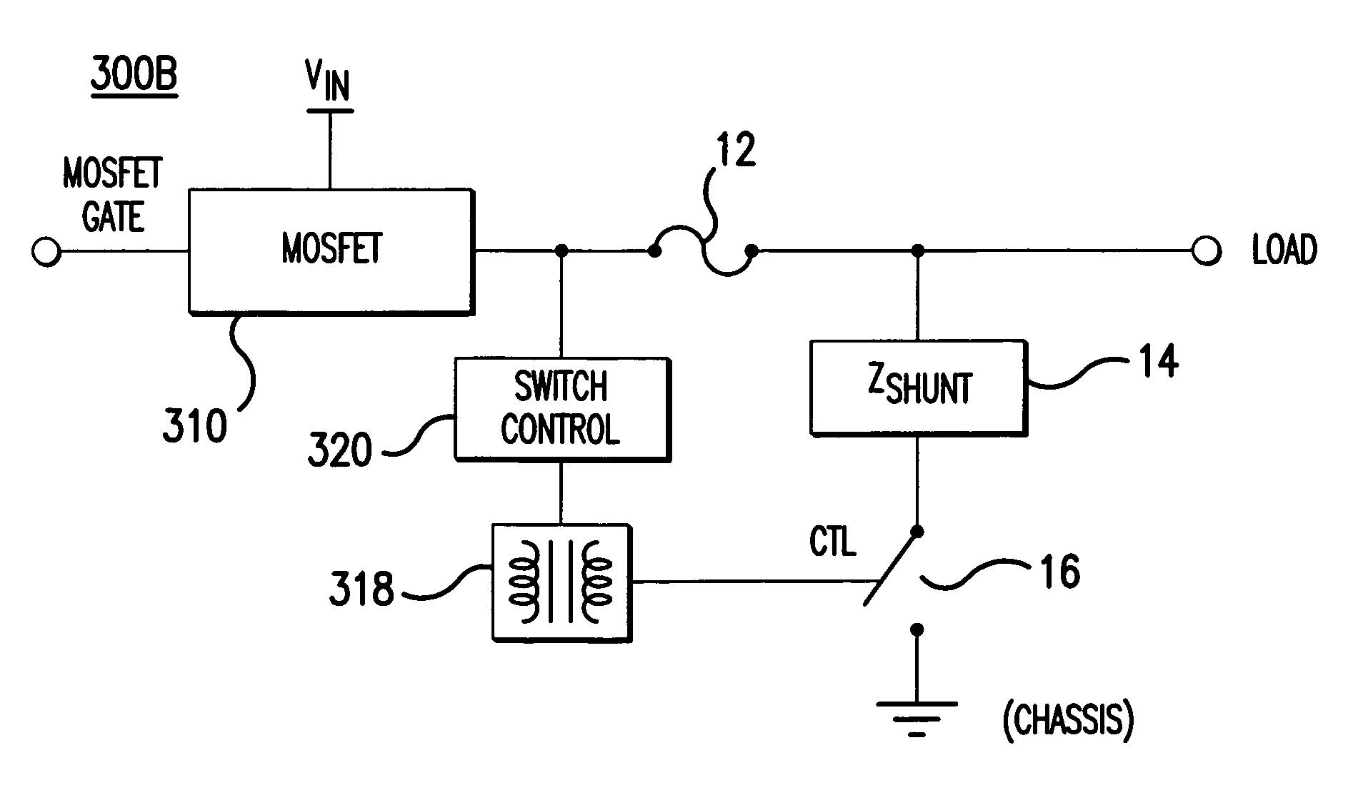
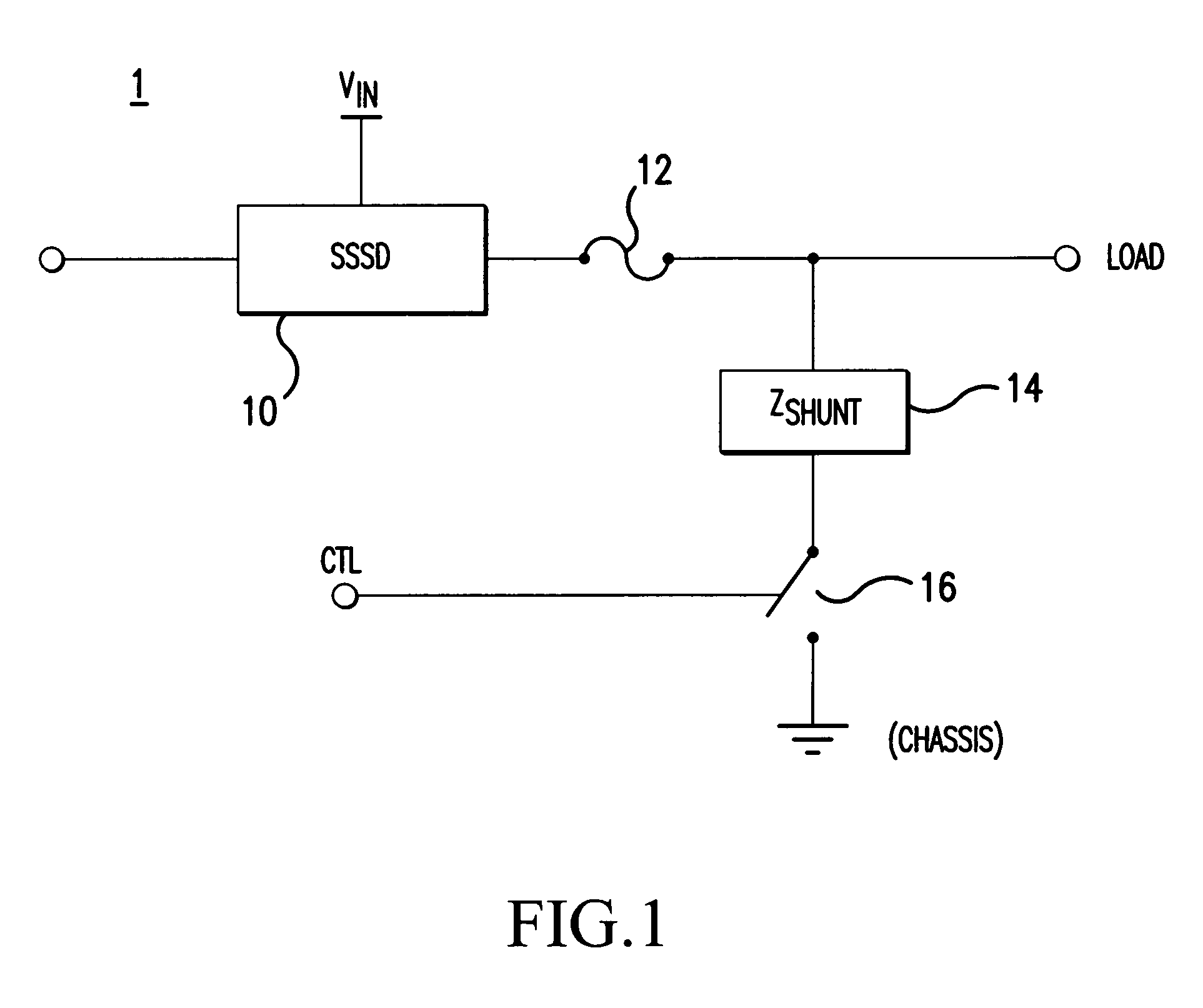
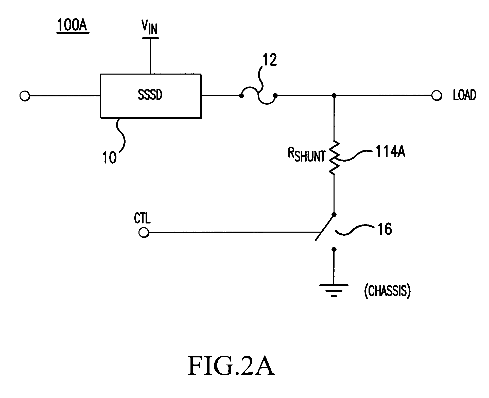
[0018]In one aspect, embodiments of the present invention relate to an apparatus and a method for shunting leakage current in an electrical power distribution system that uses solid state switching devices as relays and / or circuit breakers. With this leakage current shunting scheme, embodiments of the present invention addresses safety issues that may arise in such electrical power distribution systems. Although embodiments of the present invention are discussed below in which power MOSFETs are used as solid state switching devices (SSSDs) (also referred to as solid state relays) in an electrical power distribution system, aspects of the present invention are applicable to systems using other types of solid state switching devices. Furthermore, although aspects of the present invention are described in the context of a specific application example, it should be recognized that principles of the present invention are applicable to other implementations and environments.

Safety Conside...


PUM


Abstract

The invention provides an apparatus for shunting leakage current of a solid state switching device (SSSD) (10). The apparatus selectively provides a shunt pathway to divert current away from the output load based on the switching state of the SSSD. The apparatus may include a shunt impedance component (14) connected to the SSSD, and a switching element (16) for selectively connecting the other end of the shunt impedance component to ground based on the switching state of the SSSD. Accordingly, when the SSSD is turned off, the switching element is switched to a state that connects the shunt impedance component to ground, thereby shunting leakage current.

Description

CROSS-REFERENCES TO RELATED APPLICATIONS[0001]This non-provisional application claims priority under 35 U.S.C. § 119(e) on U.S. Provisional Application No. 60 / 695,002 filed on Jun. 30, 2005, the entire contents of which are hereby incorporated by reference.FIELD OF THE INVENTION[0002]The present invention relates to electrical power distribution, and more particularly to aspects of an electrical power distribution system that utilizes solid state switching devices as relays and / or circuit breakers to supply electrical loads.BACKGROUND OF THE INVENTION[0003]When solid state switching devices (SSSDs) (e.g., MOSFETs) are used instead of conventional electromechanical relays or circuit breakers for AC high power applications, excessive leakage current can occur when the device is in an OFF state, thereby creating a safety issue. As one example, in an aircraft secondary electrical power distribution system (SEPDS), maintenance personnel may come into contact with the open end at the outp...

Claims


Application Information

Patent Timeline
Patent Type & Authority Patents(United States)
IPC IPC(8): H01H79/00H01H3/26
CPCH02H5/12H02H9/041
Inventor YU, WENJIANGLIU, ZHENNING Z.FILIMON, DANIEL G.PLIVCIC, BORIS
Owner HONEYWELL INT INC
Why Eureka
Try Eureka