
Optical sensor and method for optically inspecting surfaces

a technology of optical inspection and optical sensor, which is applied in the direction of optical radiation measurement, instruments, photometry, etc., can solve the problems of inability to use a one hundred percent examination method of flat glass, and the defects which can be identified with this technology lie in the range of a few micrometers, so as to achieve uniform detection sensitivity

Inactive Publication Date: 2009-05-26
SIEMENS AG
View PDF18 Cites 1 Cited by
  • Summary
  • Abstract
  • Description
  • Claims
  • Application Information

AI Technical Summary

Benefits of technology

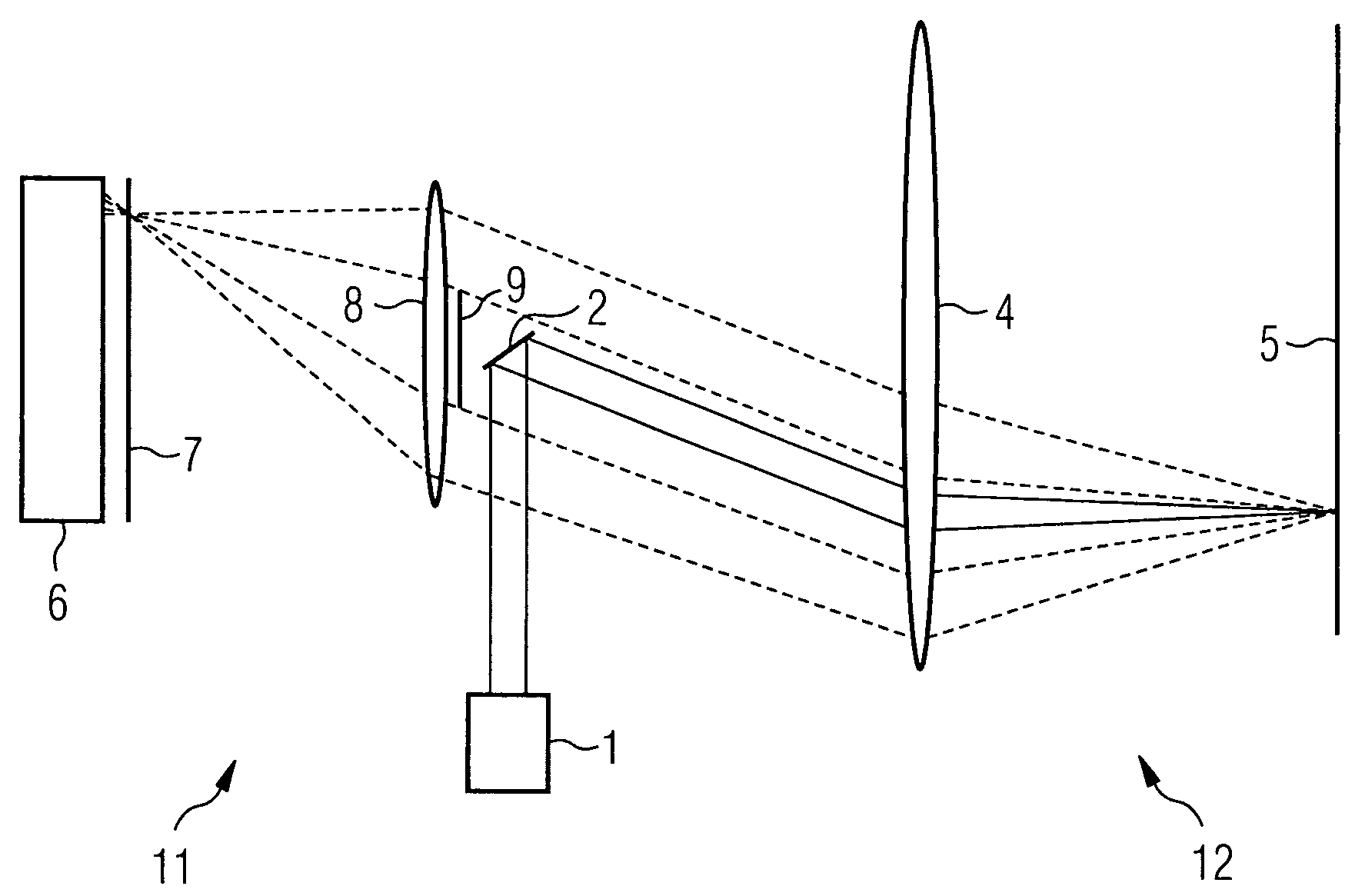
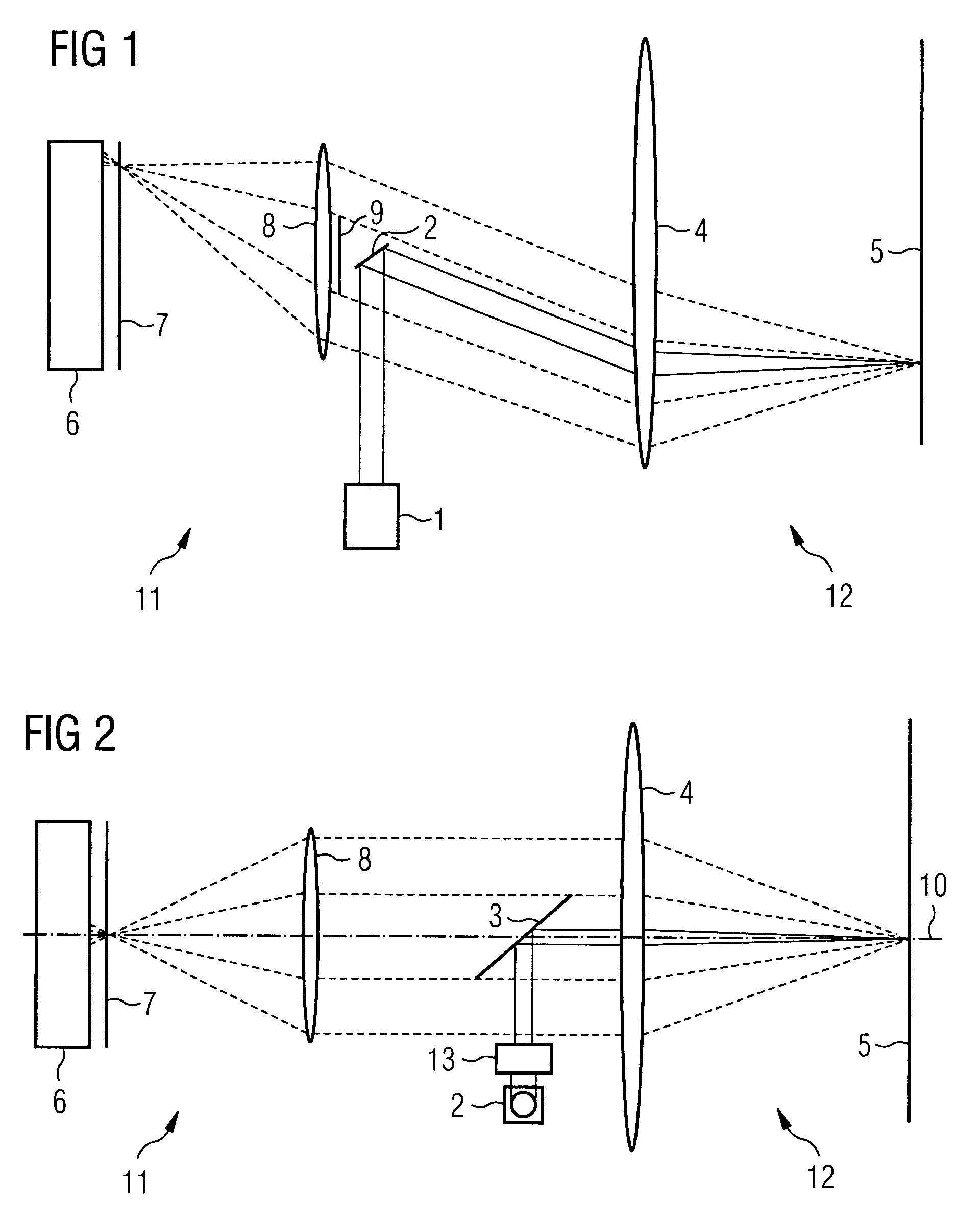
[0006]The concept underlying the invention such that a one hundred percent inspection of smooth surfaces, in particular of flat glass, for defects which can be punctiform, flat or laminar and the dimensions of which lie in the submicrometer range, is enabled by the use of a telecentric laser scanner in combination with a photomultiplier to detect the laser light scattered onto the defects. A very high detection sensitivity of the photomultiplier allows defects in the submicrometer range to be detected while maintaining a high data rate. In this way, a complete final inspection of smooth surfaces and / or flat glass is possible. Both the scanning illumination beam and also the detection beam path are arranged telecentrically. This allows the scattered light emanating from a defect to be captured by way of an aperture which is rotationally symmetrical to the illumination direction, which is identical to the measurement direction, as a result of which particularly fine scratches are identified over the surface irrespective of their positions on a surface in consideration of the same sensitivity. The optical construction of the sensor is very simple, since the resolution of the sensor is only determined by the focal diameter of the scanning beam. For this reason, the imaging quality of the optical scanning system must only be adjusted to the aperture of the scanning beam which is minimal in comparison with the detection beam path. The back scattered light is collected by way of an optical detection system, and the imaging quality of the optical detection system is not subject to any particular standards.
[0008]A diaphragm of this type in the center of the optical detector system blocks the light reflected in a mirror-like manner by a glass specimen surface for instance, said light being passed back onto the illumination path by virtue of the telecentric illumination. The size of the diaphragm provided here enables a certain angular tolerance of the glass specimen to the vertical illumination direction. An annular design, in other words a design of the detector aperture which is rotationally symmetrical to the optical axis, is realized by the central diaphragm irrespective of the position of the scanning beam. The advantage of this annular aperture simultaneously enables a uniform detection sensitivity for linear defects irrespective of their direction on the measurement surface.

Problems solved by technology

The defects which can be identified with this technology lie in the range of a few micrometers.
This method can however not be used for a one hundred percent examination of the flat glass in the production cycle.

Method used


Image

  • Optical sensor and method for optically inspecting surfaces
  • Optical sensor and method for optically inspecting surfaces

Examples


Embodiment Construction

[0015]FIG. 1, which reproduces the main design of a described sensor, shows that the collimated light of a laser is deflected from a scanner in a specific angular range. A laser 1 generates a laser beam, which is deflected by means of a scanning mirror 2. A telecentric optical scanning system 4 focuses the deflected light onto the smooth surface 5 to be examined or onto a glass specimen. The light beams hit the surface perpendicularly, and as a result of the deflection of the scanning mirror, the laser focus on the surface describes a line. The laminar scanning of the glass specimen is achieved by the infeed of the specimen perpendicular to the scanning line. The scattered light reflected by the glass surface is collimated by the telecentric optical scanning system 4 and is focused onto a slit diaphragm 7 using a downstream optical detector system 8. The focused light flows through the slit diaphragm 7 and hits the receiving surface of a photomultiplier 6. The slit diaphragm 7 arran...


PUM

PropertyMeasurementUnit
angleaaaaaaaaaa
transparentaaaaaaaaaa
depthsaaaaaaaaaa

Abstract

In one aspect, an optical sensor is used to detect defects, which can appear on smooth surfaces, is provided. The sensor includes a telecentric laser scanner and a detection unit. The scanner includes a laser for the approximately perpendicular illumination of a smooth surface, a scanning mirror, and a telecentric optical system for guiding illumination and detection beams the detection unit includes an optical detector system, a central diaphragm, which is concentrically positioned in the vicinity of the optical detector system in the direction toward the telecentric laser scanner, a highly sensitive photomultiplier for detecting scattered light, which emanates from defects on smooth surfaces, and a slit diaphragm arranged upstream of the photomultiplier.

Description

CROSS REFERENCE TO RELATED APPLICATIONS[0001]This application claims priority of German application No. 102006019468.3 DE filed Apr. 26, 2006, which is incorporated by reference herein in its entirety.FIELD OF INVENTION[0002]The invention relates to a method and an arrangement for detecting defects on smooth surfaces, with defects that exhibit dimensions in the range of less than 1 μm being treated.BACKGROUND OF INVENTION[0003]Monitors or televisions having cathode ray tubes are being increasingly squeezed out of the market by flat screens. The flat glass used for flat screens of this type must correspond to particular standards and must, in particular, be defect free, it being possible for both surface sides of a flat glass panel to be viewed. In this way, the glass side, which is provided with electrical terminals and can thus be processed photolithographically, is to be inspected against different standards to the side of the flat glass panel pointing outwards. All in all, a comp...

Claims


Application Information

Patent Timeline
Patent Type & Authority Patents(United States)
IPC IPC(8): G01N21/88
CPCG01N21/8901G01N21/896G01N33/386G01N21/958G01N2021/4716G01N2021/4735G01N2021/8905G01N2201/0642G01N2201/1042G01J1/02
Inventor HEINE, WOLFGANGSPRIEGEL, DIETERSTOCKMANN, MICHAELWEBER, MARTIN
Owner SIEMENS AG
Learn More