
Method and system for transmitting and receiving packets

a packet and header technology, applied in the field of data packet header compression and decompression, can solve the problems of inability to accurately predict information, loss of synchronization with the compressor, and no longer correctly rebuilding packets, so as to improve the performance of packet transmission and reception, and improve the transmission and reception of packets.

Inactive Publication Date: 2009-05-26
NOKIA CORP
View PDF18 Cites 38 Cited by
  • Summary
  • Abstract
  • Description
  • Claims
  • Application Information

AI Technical Summary

Benefits of technology

The solution provides improved transmission and reception performance by eliminating wrap-around issues and enabling robust header compression, maintaining sequence synchronization, and reducing bandwidth usage in wireless communications.

Problems solved by technology

Because the media normally varies in unpredictable ways, this information cannot be truly predicted.
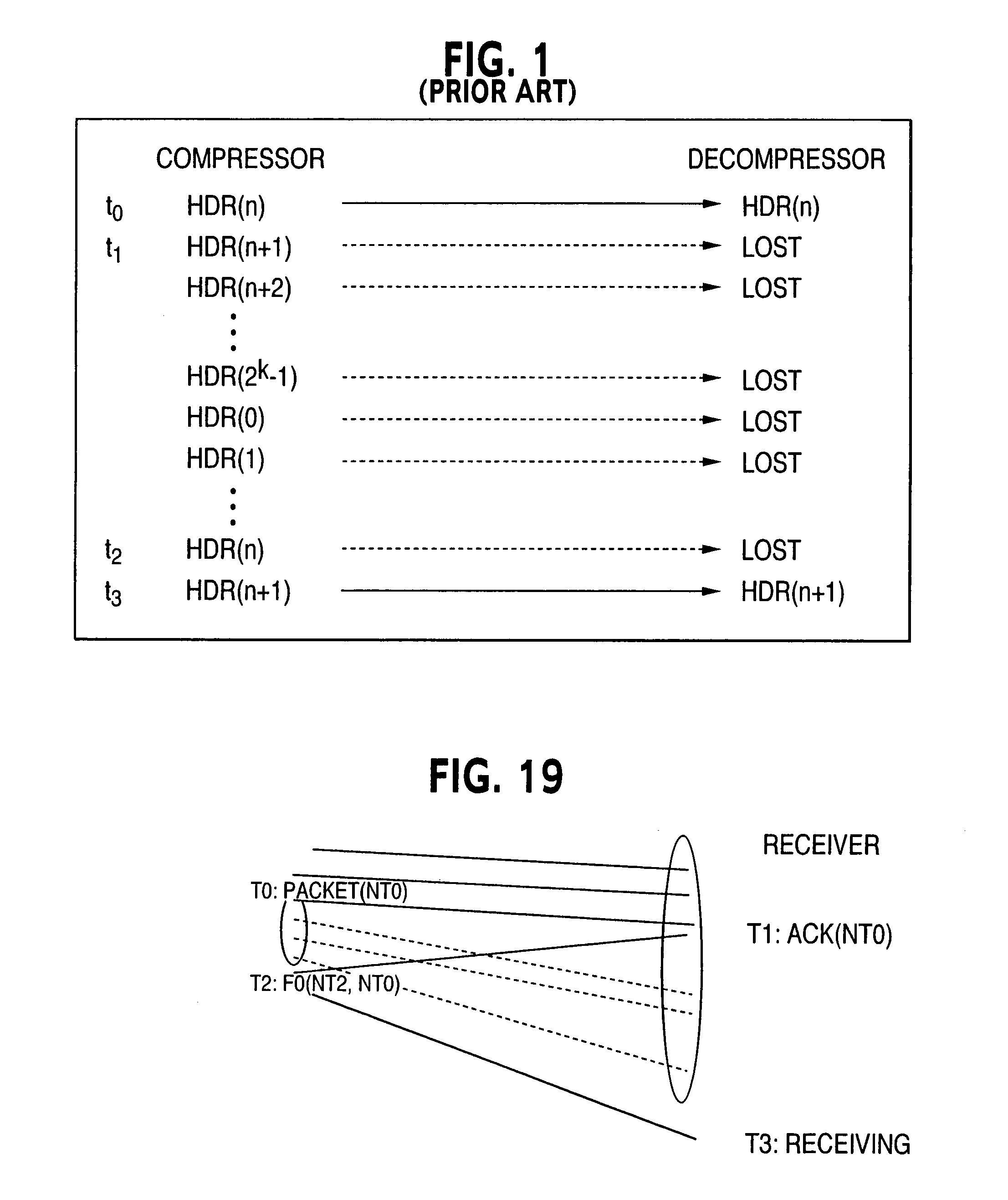
When packets are lost or corrupted, the decompressor can lose synchronization with the compressor such that it can no longer correctly rebuild packets.
Loss of synchronization can occur when packets are dropped or corrupted during transmission between compressor and decompressor.
This type of header is the least optimal to send due to its large size (e.g., 40 bytes for IPv4).
Transmission of additional FH packets has adverse effects on the efficiency of the compression algorithm.
Such an event results in some unexpected change in the RTP time stamp value, and a need to update the RTP time stamp at the receiver by a value other than the current FOD.
However, the header compression defined in RFC 2508 is not well suited for certain environments (such as cellular or wireless environments), where bandwidth is at a premium and errors are common.
RFC 2508 suffers from lack of robustness to withstand header errors or losses, because the decompression of the current header can only be done if the immediately preceding header was also received without error and decompressed.
The header compression defined in RFC 2508 is not well suited for cellular environments, where bandwidth is at a premium and long error bursts are not uncommon.
Large size headers consume bandwidth and create peaks in the bandwidth demand which are more difficult to manage.
Just using a short sequence number (one with a limited number of bits) to detect packet loss is not robust to an error-prone network, such as in a wireless network where long loss may happen at any time.

Method used


Image

  • Method and system for transmitting and receiving packets
  • Method and system for transmitting and receiving packets
  • Method and system for transmitting and receiving packets

Examples


first embodiment

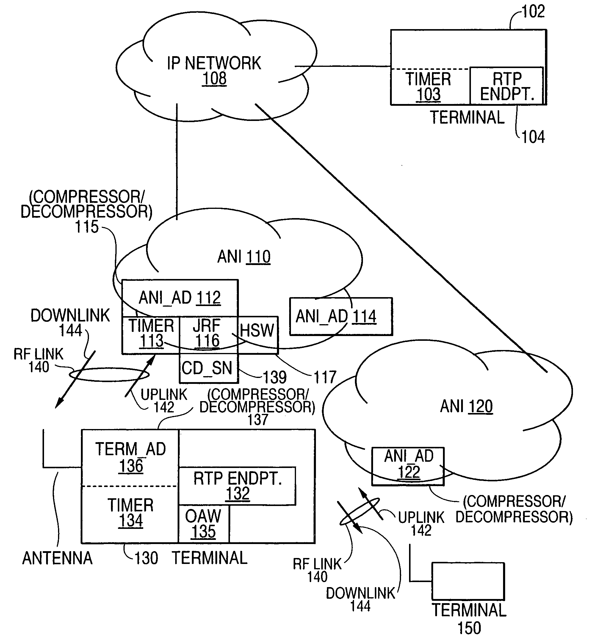
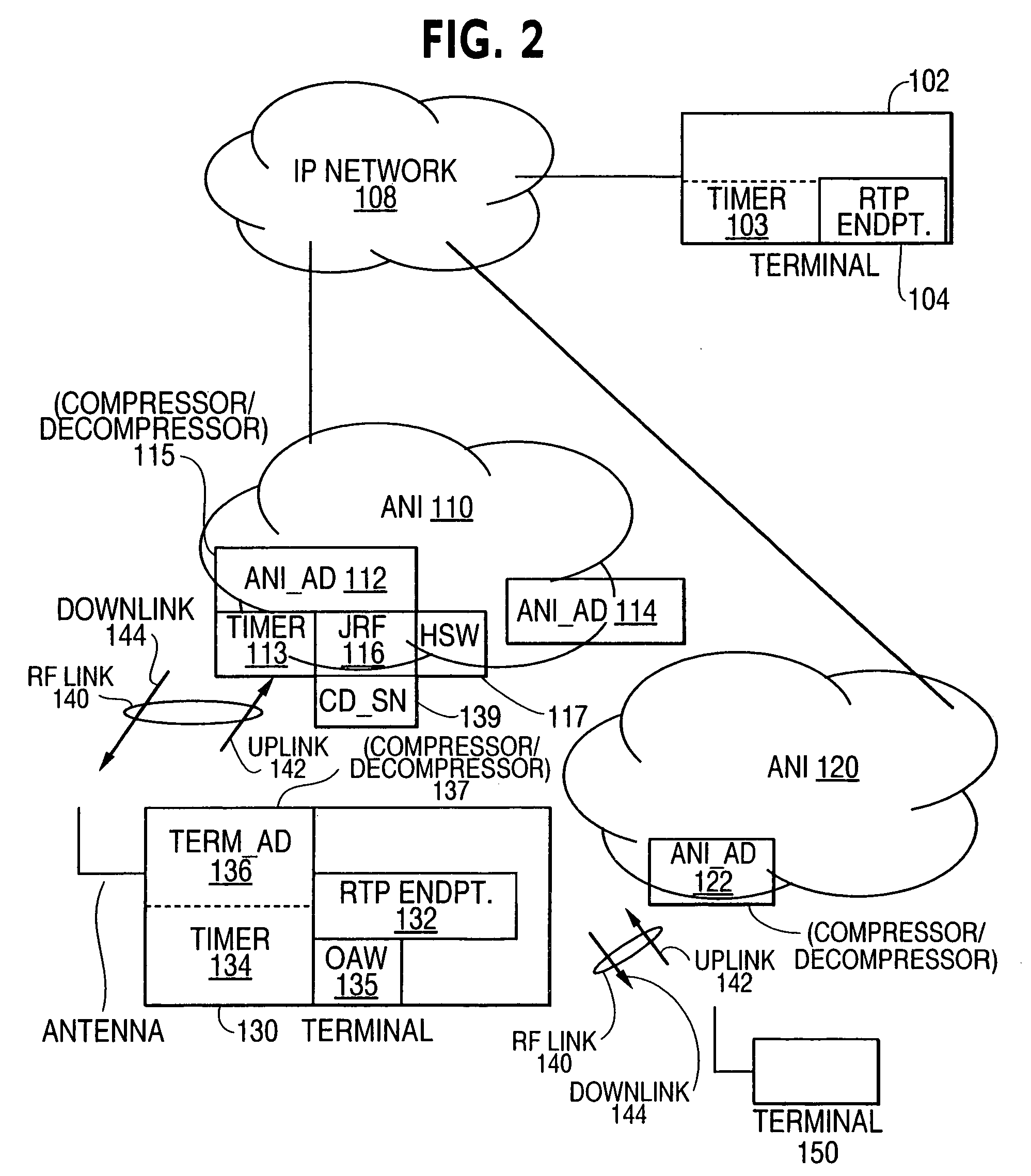
[0142]the invention, which may be practiced with the system of FIG. 2, increases the probability of reception of FH and FO type packets so that there is a timely progression towards the most optimal SO state. The probability of reception may be increased by applying additional error protection to the FH and FO packets in the form of[0143]Error Correcting Codes[0144]Error Correcting Codes+Interleaving[0145]Duplicate Transmission of FH and FO header data

[0146]The first embodiment of the invention provides extra protection against loss of data packets over a lossy transmission medium, e.g. wireless without allocating additional channel resources to the compressor and decompressor. The extra bandwidth is obtained by delaying transmission of the data stream by some interval of time, ‘T’, as illustrated in FIGS. 5A and 5B, such that there is enough time to send the extra data packets. The delay interval can be used to send initial FH packets, and FO packets at any time.

[0147]Transmission ...

second embodiment

[0155]the invention, which may be practiced with the system of FIG. 2, is based upon IP / UDP / RTP fields most of the time being either constant or can be extrapolated in a linear fashion. In those instances, the compressed header just carries a multiple non extended sequence number having k bits that provides sufficient information for linear extrapolation. Like RFC 2508, with the invention when linear extrapolation results in incorrect header reconstruction, the transmitter sends FO difference information. Unlike RFC 2508, the difference information is calculated with respect to a reference packet known to be correctly received, rather than the one immediately preceding the current packet. This feature ensures that the current header can be reliably reconstructed even if one or more past packets were lost. Since the header can be reliably reconstructed in that manner, there is no need to send a full header. The reference is determined and updated by the compressor of the receiver acc...

case 1

sub>1), SO(n2)

Case 2: HDR(n1), FO(n2)

Long Loss Detection and Recovery for Case 1

[0175]To detect whether or not there is long loss in case 1, a timer (e.g. timer 134) is maintained at the compressor, and it is checked and updated whenever a packet is received.

[0176]Let[0177]T be the time when HDR(n1) is received[0178]T+ΔT be the time when HDR(n2) is received

[0179]The compressor sends SO packets only if the one or more preceding FH or FO packets have been acknowledged, and also linear extrapolation applies from the acknowledged header. Therefore, If HDR(n2) is SO and no matter what type HDR(n1) is, linear extrapolation applies from HDR(n1) to HDR(n2). This basically means that the RTP time stamp and RTP sequence number for packet n1 through n2 when generated at the compressor, closely follows a linear pattern as a function of the time of day clock. Consequently, the headers coming into the decompressor also follow a linear pattern as a function of time, but with fluctuation due to jit...


PUM


Abstract

The invention is a system and method for synchronizing the transmission of compressed headers in data packets between a transmitter and a receiver having a preferred wireless application which is an improvement of RFC2508. In a system having a transmitter transmitting a plurality of packets each containing a header to a receiver, a method of synchronizing the transmission of compressed headers between the transmitter and receiver in accordance with the invention includes transmitting a current packet from the transmitter to the receiver containing information that the transmitter is prepared to send subsequently transmitted packets in which the headers therein are to be compressed in comparison to the header contained in the current packet; and transmitting from the receiver to the transmitter an acknowledgment packet that the receiver has received the current packet.

Description

CROSS REFERENCE TO RELATED APPLICATIONS[0001]This application is a divisional application of application Ser. No. 09 / 536,639, filed Mar. 28, 2000 now U.S. Pat. No. 6,882,637 which application is incorporated herein by reference in its entirety.[0002]This application claims the filing date of US. provisional application Ser. No. 60 / 159,360, filed Oct. 14, 1999, entitled “Method and System for Transmitting and Receiving Data Packets”.[0003]Reference is also made to U.S. patent application Ser. No. 09 / 522,497, entitled “An Efficient Handoff Procedure for Header Compression”, filed on Mar. 9, 2000, which application is incorporated herein by reference in its entirety.[0004]Reference is also made to U.S. patent application Ser. No. 09 / 536,638, entitled “Variable Length Encoding of Compressed Data”, filed on even date herewith, which application is incorporated herein by reference in its entirety.BACKGROUND OF THE INVENTION[0005]1. Field of the Invention[0006]The present invention relates...

Claims


Application Information

Patent Timeline
Patent Type & Authority Patents(United States)
IPC IPC(8): H04L12/56G06F15/16H04N7/14H04L1/18H04L29/06
CPCH04L1/1809H04L1/1854H04L29/06H04L69/04H04L69/22H04L9/40
Inventor LE, KHIEMCLANTON, CHRISTOPHERZHENG, HAIHONGLIU, ZHIGANG
Owner NOKIA CORP
Learn More