Multifunctional Antenna Module For Use with a Multiplicity of Radiofrequency Signals

a radiofrequency signal and antenna module technology, applied in the field of antennas, can solve the problems of not being suitable to simultaneously cover antenna modules, antenna modules are not suitable to simultaneously cover antennas, etc., and achieve the effect of reducing size, maximizing the difference between surface sizes, and reducing siz

Inactive Publication Date: 2011-06-16
CALEARO ANTENNE SRL
View PDF3 Cites 3 Cited by
  • Summary
  • Abstract
  • Description
  • Claims
  • Application Information

AI Technical Summary

Benefits of technology

[0033]By this arrangement, the same number of signal frequencies may be handled using an upper patch antenna of reduced size, so that the lower patch antenna can be exposed as much as possible. This is because, considering the same number of signal frequencies to be handled, a patch antenna having a circular antenna structure affords a 16% size reduction as compared with an identical patch antenna having a polygonal antenna structure. Thus, the provision of an antenna structure having a circular surface allows the use of an upper patch antenna of a smaller size than in prior art embodiments that use patch antennas with polygonal antenna structures only. Furthermore, the provision of an antenna structure having a polygonal surface allows the use of a lower patch antenna of a larger size than in prior art embodiments that use patch antennas with circular antenna structures only.
[0034]In short, the implementation of such a configuration can maximize the difference between the surface sizes of the lower patch antenna and the upper patch antenna, thereby optimizing the operation of the lower patch antenna.

Problems solved by technology

Nevertheless, these antenna modules are not suitable to simultaneously cover both applications that require handling of integer harmonics of the fundamental frequency and applications that require such harmonics to be cut off.
Furthermore, this antenna module also suffers from the drawback of not being suitable to simultaneously cover both applications that require handling of integer harmonics of the fundamental frequency and applications that require such harmonics to be cut off.

Method used


Image

  • Multifunctional Antenna Module For Use with a Multiplicity of Radiofrequency Signals
  • Multifunctional Antenna Module For Use with a Multiplicity of Radiofrequency Signals
  • Multifunctional Antenna Module For Use with a Multiplicity of Radiofrequency Signals

Examples


Embodiment Construction

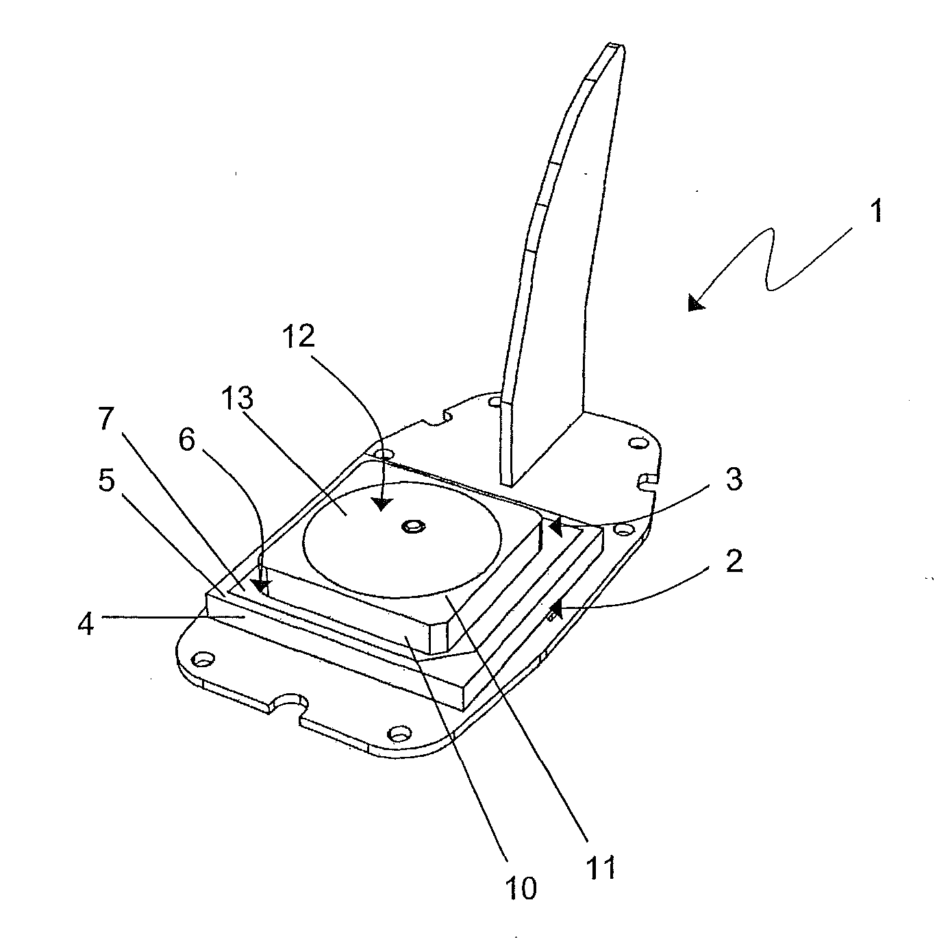
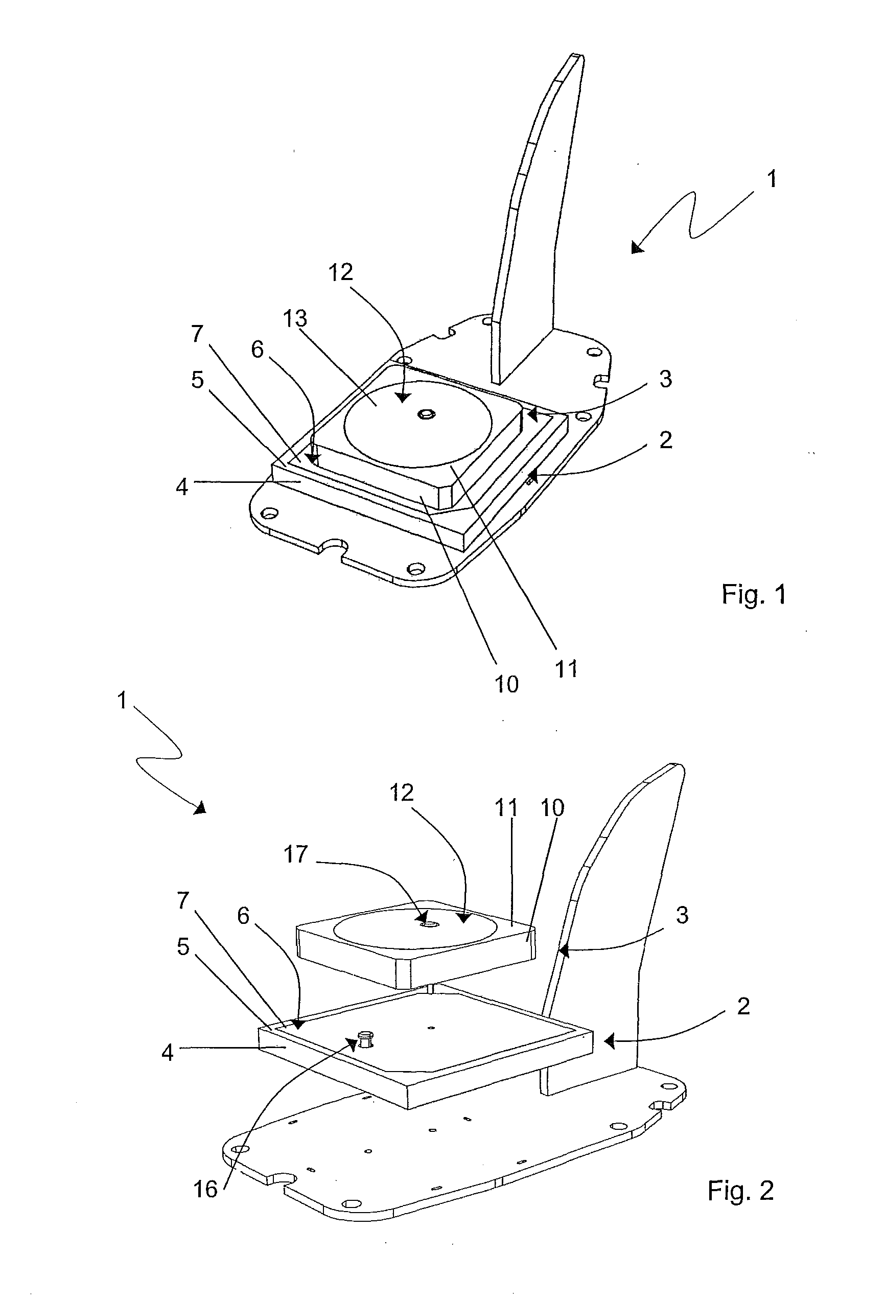
[0038]Referring to FIG. 1, there is shown an antenna module 1 of the invention adapted to be secured to a vehicle or similar means of transport.

[0039]Particularly, the module 1 comprises a first patch antenna 2, with a second patch antenna 3 disposed thereabove. This embodiment shall be intended merely as an example and not as a limitation to different embodiments, in which there are more than two stacked patch antennas.

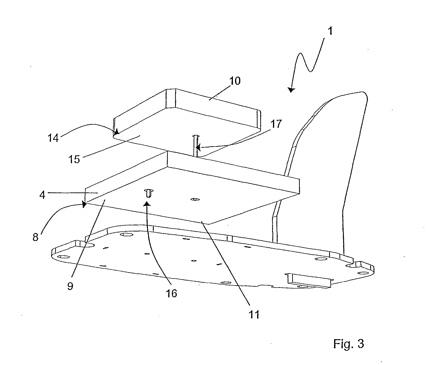
[0040]In greater detail, also referring to FIGS. 2 and 3, the first patch antenna 2 is shown to comprise a first dielectric substrate 4 having a top surface 5 with a first antenna structure 6 made of a first electrically conductive layer 7 laying thereon, and a bottom surface 8 with a second layer of electrically conductive material 9 thereon.

[0041]Likewise, the second patch antenna 3 comprises a second dielectric substrate 10 having a top surface 11 with a second antenna structure 12 made of a third electrically conductive layer 13 laying thereon, and a bottom surfa...


PUM


Abstract

An antenna module for receiving a multiplicity of radiofrequency signals comprises a first patch antenna (2) with a second patch antenna (3) disposed above it. The first patch antenna (2) comprises a first dielectric substrate (4) having a top surface (5) with a first antenna structure (6) made of a first electrically conductive layer (7) laying thereon, and a bottom surface (8) with a second layer of electrically conductive material (9) thereon. The second patch antenna (3) comprises a second dielectric substrate (10) having a top surface (11) with a second antenna structure (12) made of a third electrically conductive layer (13) laying thereon, and a bottom surface (14) with a fourth layer of electrically conductive material (15) thereon. One of the first (6) and second antenna structures (12) has a substantially circular or elliptical surface, and the other has a substantially polygonal surface.

Description

FIELD OF THE INVENTION[0001]The present invention finds application in the field of antennas for vehicles or movable means of transport and relates to an antenna module for receiving a multiplicity of radiofrequency signals.[0002]Particularly, the present invention discloses an antenna module comprising two or more microstrip antennas, also known as patch antennas, which are particularly suitable for receiving and / or transmitting satellite band radiofrequency signals.BACKGROUND ART[0003]There is a well-known need, particularly in vehicles, of using a plurality of antennas adapted to receive and / or transmit radiofrequency signals in various frequency bands.[0004]Particularly, these antennas may be adapted to receive and / or transmit AM, FM, DAB, TV, GPS, GSM, UMTS band signals and others. These antennas are often arranged close to each other to minimize space requirements and allow them to be enclosed in a single casing.[0005]A particular type of radiofrequency signals are those for s...

Claims


Application Information

Patent Timeline
Patent Type & Authority Applications(United States)
IPC IPC(8): H01Q21/00
CPCH01Q1/3275H01Q21/28H01Q9/0407
Inventor TONIOLO, ENRICOAMATORI, DAVIDE
Owner CALEARO ANTENNE SRL
Why Eureka
Try Eureka