Thermal module

a technology of thermal modules and heat dissipation tubes, applied in the direction of cooling/ventilation/heating modifications, semiconductor/solid-state device details, semiconductor devices, etc., can solve the problems of copious amount of heat generated by modern electronic packages, and achieve the effect of low cost for forming the frame and low cost for the heat dissipation tub

Active Publication Date: 2009-06-02
CHAMP TECH OPTICAL FOSHAN
View PDF26 Cites 22 Cited by
  • Summary
  • Abstract
  • Description
  • Claims
  • Application Information

AI Technical Summary

Benefits of technology

[0005]According to a preferred embodiment of the present invention, a thermal module comprises a heat spreader for contacting with a heat-generating electronic device mounted on a printed circuit board, a heat sink, a heat pipe thermally connecting the heat spreader and the heat sink. A frame is detachably mounted on the heat spreader, for fixing the heat spreader to the printed circuit board so that the heat spreader can thermally contact with the heat-generating device on the printed circuit board. The frame is made by stamping a metal sheet or plastics injection molding. The heat spreader has a simple polygonal configuration. Accordingly, the cost for forming the frame and the heat spreader is low.

Problems solved by technology

Modern electronic packages generate copious amounts of heat.

Method used


Image

  • Thermal module
  • Thermal module
  • Thermal module

Examples


Embodiment Construction

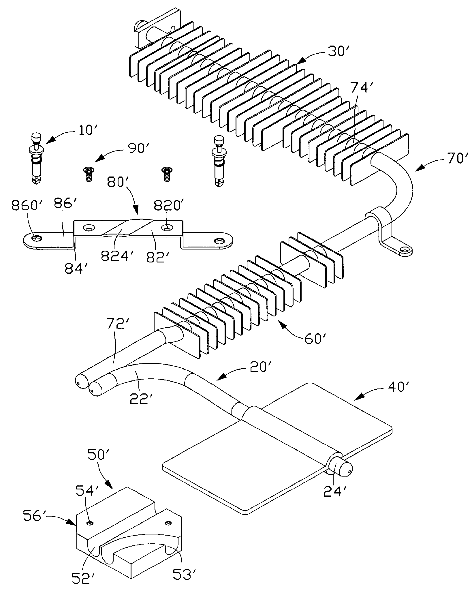
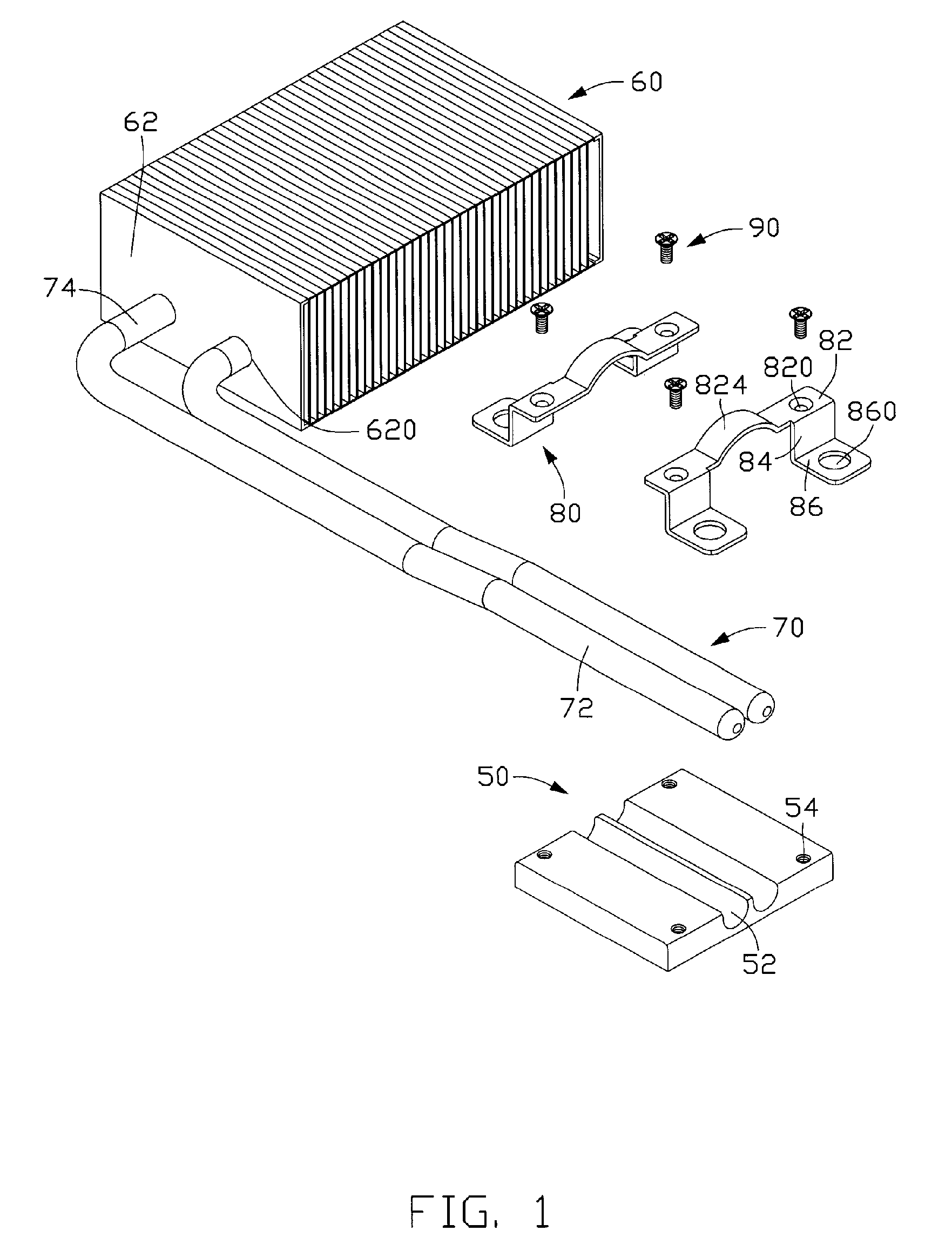
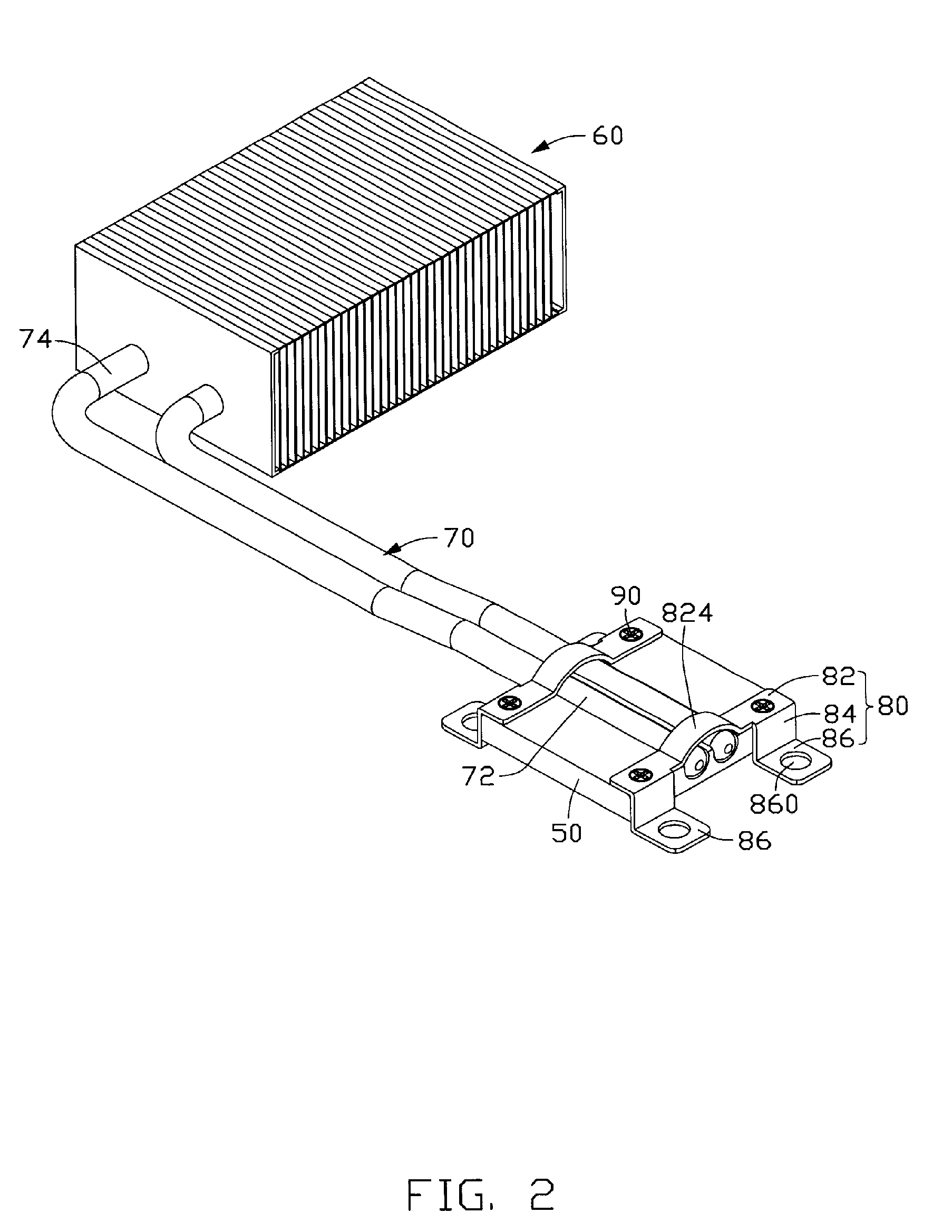
[0012]FIGS. 1 and 2 show a thermal module in accordance with a preferred embodiment of the present invention. The thermal module comprises a heat spreader 50, a heat sink 60 and a pair of parallel heat pipes 70 thermally connecting the heat spreader 50 and the heat sink 60. A pair of frames 80 is detachably mounted at two opposite lateral sides of the heat spreader 50.

[0013]The heat spreader 50 is made of metallic material with good heat conductivity such as copper, for thermally engaging with a heat generating electronic device. The heat spreader 50 has a rectangular configuration, and defines a pair of parallel and straight grooves 52 at a central top thereof. A threaded hole 54 is defined at each of four corners of the heat spreader 50.

[0014]The heat sink 60 comprises a plurality of fins 62 spaced from and connected with each other. The fins 62 extend perpendicularly to the heat spreader 50. A pair of through holes 620 is defined in the fins 62.

[0015]Each of the heat pipes 70 is ...


PUM


Abstract

A thermal module includes a heat spreader (50) for contacting with a heat-generating electronic device mounted on a printed circuit board, a heat sink (60), a heat pipe (70) thermally connecting the heat spreader and the heat sink. A frame (80) is detachably mounted on the heat spreader, for fixing the heat spreader to the printed circuit board so that the heat spreader can thermally contact with the heat-generating device on the printed circuit board. The heat spreader has a simple polygonal configuration. The frame is formed by stamping a metal sheet or plastics injection molding.

Description

FIELD OF THE INVENTION[0001]The present invention relates to a thermal module having a heat spreader contacting with a heat-generating electronic element mounted on a printed circuit board, wherein a frame detachably mounted on the heat spreader for fixing the heat spreader to the printed circuit board.DESCRIPTION OF RELATED ART[0002]With the continued development of computer technology, electronic packages such as computer central processing units (CPUs) are generating more and more heat that needs to be dissipated immediately to avoid damage to the circuitry. Therefore, thermal modules are widely used to remove heat from the electronic packages of the computer. Modern electronic packages generate copious amounts of heat. At the same time, modern computers and their electronic packages are continually being miniaturized. Thus, compact thermal modules with good heat dissipation efficiency are increasingly being used.[0003]As shown in FIG. 5, a conventional thermal module includes a ...

Claims


Application Information

Patent Timeline
Patent Type & Authority Patents(United States)
IPC IPC(8): H05K7/20
CPCH01L23/427H01L2924/0002H01L2924/00
Inventor ZHAO, LIANG-HUIWU, YI-QIANG
Owner CHAMP TECH OPTICAL FOSHAN
Why Eureka
Try Eureka