
Fully automatic, head mounted, hand and eye free camera system and photography

a camera system and camera head technology, applied in the field of fully automatic, head mounted, hand and eye free camera system and photography, can solve the problems of not being able to capture the scenery the user's eyes are really seeing, film camera is too big and heavy to mount on the human head, etc., and achieves the effect of convenient and convenient way to take pictures or record

Inactive Publication Date: 2009-06-02
LEI TIANMO
View PDF3 Cites 51 Cited by
  • Summary
  • Abstract
  • Description
  • Claims
  • Application Information

AI Technical Summary

Benefits of technology

Enables hands and eyes-free photography and video recording, ensuring 'what you see is what you get' with continuous, real-time automatic processes, suitable for all ages and conditions, including when the user is engaged in other activities.

Problems solved by technology

There are lots of patents involving the head mounted camera, but none of them was really used commercially.
The films camera is too big and too heavy to mount on the human's head.
Although ccd and cmos sensor are widely adopted, almost all of patents relate to head mounted camera are short of automatic aiming and focusing, thereby cannot capture the scenery the user's eyes are really seeing.
The U.S. Pat. No. 6,307,526 proposed the idea of using eye tracker; but the size of lens, the visual field of the lens and the angle of the lens can be turn around are limited.
Another weakness of this patent is that at least one eye of the user must gaze at the viewfinder constantly.
This patent also not use portable personal computer, lacks powerful compute and control ability to realize automatic aiming and focusing automatically, continuously and in the real time, lacks huge memory to store the pictures and video.

Method used


Image

  • Fully automatic, head mounted, hand and eye free camera system and photography
  • Fully automatic, head mounted, hand and eye free camera system and photography
  • Fully automatic, head mounted, hand and eye free camera system and photography

Examples


Embodiment Construction

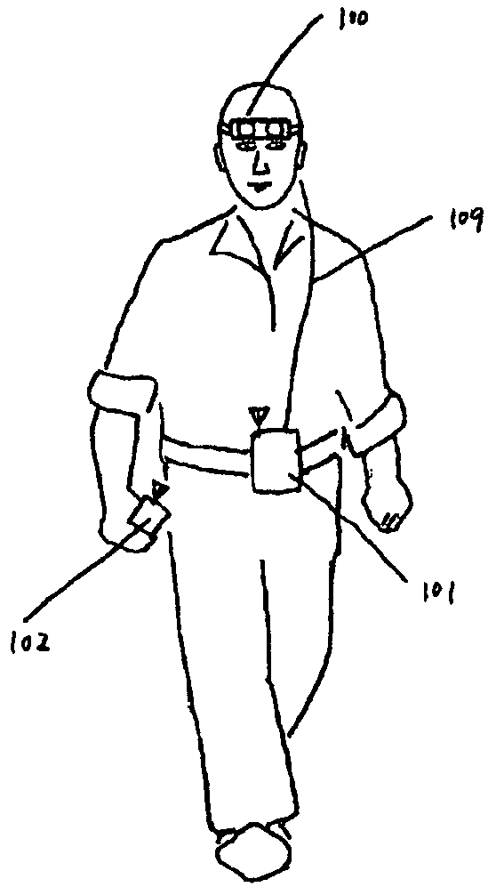
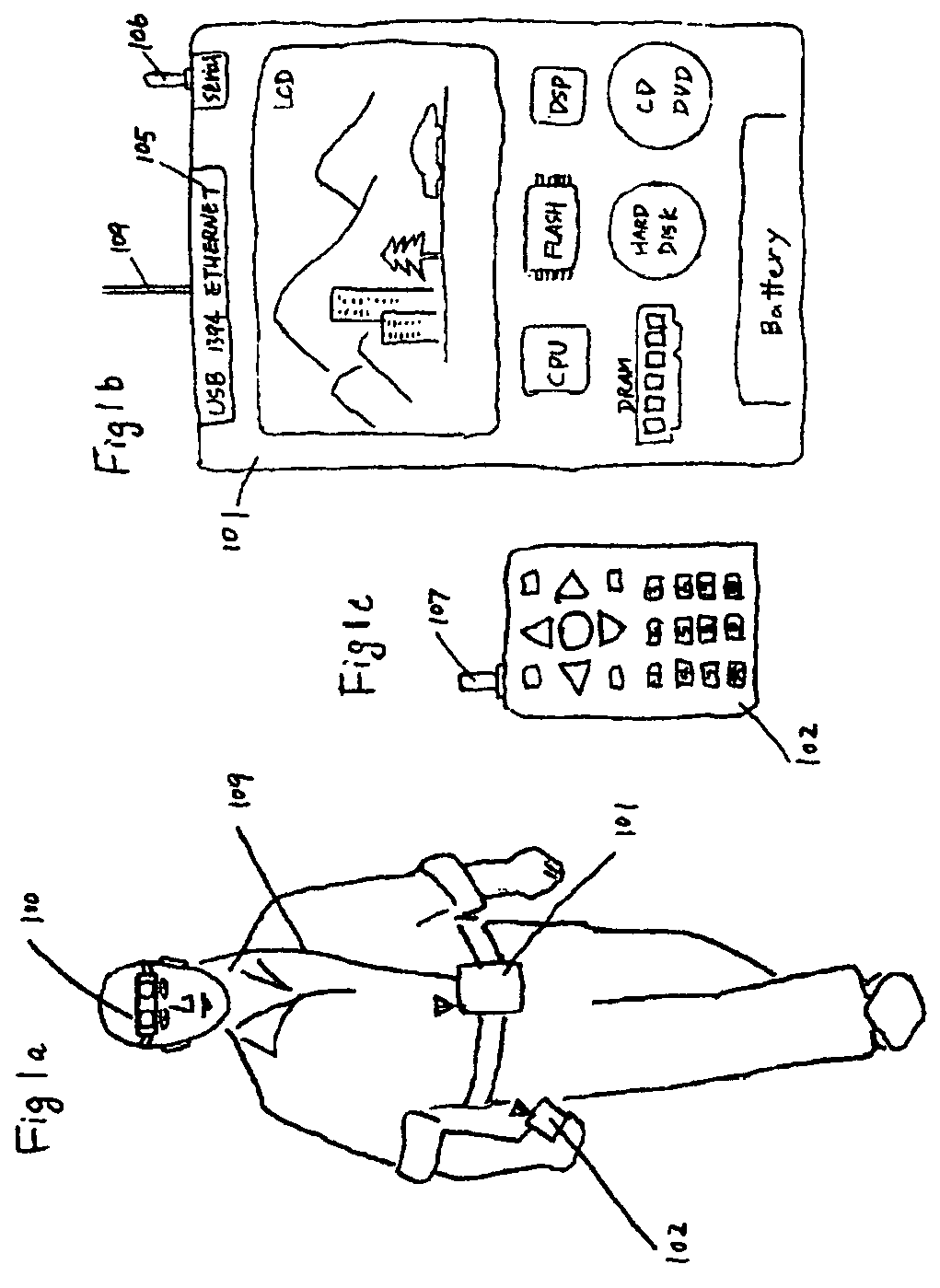
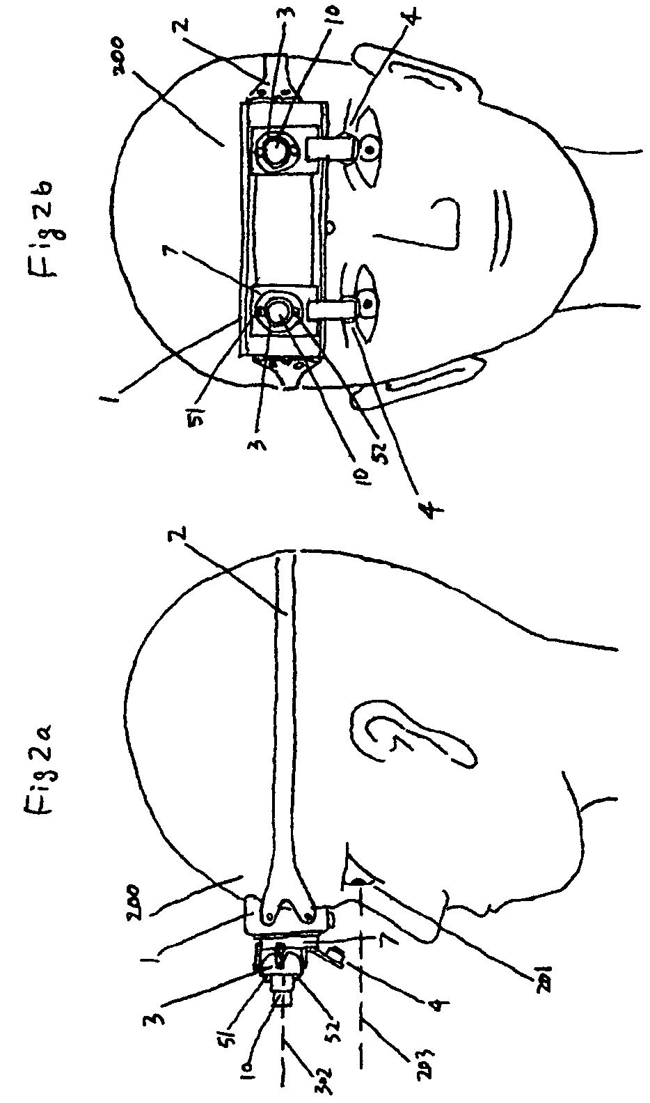
[0016]As showed in FIG. 1a, the full automatic, head mounted, hand and eye free camera system comprises a head mounted camera header 100, a portable personal computer 101, and a hand hold controller 102. The head mounted camera header is attached on the forehead right above the eyes. controlled by a portable personal computer, head mounted camera header always automatically aims at and focuses on the target the eyes are seeing; continuously takes pictures and transmits them to the portable personal computer without any assistance of hands and eyes. The only thing user have to do is to press the shoot button on hand hold controller to instruct portable personal computer to take a picture. The portable personal computer save this picture captured by head mounted camera header to a directory in which the sound is recorded five seconds before and after the moment the button being pressed, so there will be a picture with a corresponding sound. The user can also press a record button on h...


PUM


Abstract

A fully automatic, head mounted, hand and eye free camera System and photography are disclosed. The fully automatic, head mounted, hand and eye free camera System consist of three components: A) a head mounted camera header, B) a portable personal computer, and C) a hand hold controller. The component A (head mounted camera header) is composed of two set of eye ball trackers / range finder / digital camera headers. The component B (portable personal computer) control eye ball tracker and the range finder to determine the direction of eye sight and the distance between the eye and the target, and adjusts the lens of the digital camera header to aim at and focus on target to take pictures or record video and to save the pictures or video to the storage of the portable personal computer. The user control whole system by pressing the buttons at component C (hand hold controller). The aiming, focusing, and the capturing procedure is automatic, continuous, and in the real time, and is a true process of “What you see is what you get (photo or video)”.

Description

FIELD OF THE INVENTION[0001]The head mounted commercial digital camera, camcorder and the photography.BACKGROUND OF THE INVENTION[0002]There are lots of patents involving the head mounted camera, but none of them was really used commercially. The films camera is too big and too heavy to mount on the human's head. Although ccd and cmos sensor are widely adopted, almost all of patents relate to head mounted camera are short of automatic aiming and focusing, thereby cannot capture the scenery the user's eyes are really seeing. The U.S. Pat. No. 6,307,526 proposed the idea of using eye tracker; but the size of lens, the visual field of the lens and the angle of the lens can be turn around are limited. Another weakness of this patent is that at least one eye of the user must gaze at the viewfinder constantly. This patent also not use portable personal computer, lacks powerful compute and control ability to realize automatic aiming and focusing automatically, continuously and in the real ...

Claims


Application Information

Patent Timeline
Patent Type & Authority Patents(United States)
IPC IPC(8): G03B13/20
CPCG02B27/0093G03B13/10G03B13/20G03B13/32G03B17/00G03B17/56
Inventor LEI, TIANMO
Owner LEI TIANMO
Learn More