Assembly structure

a technology of assembly structure and structural body, which is applied in the direction of dismountable cabinets, coupling device connections, furniture parts, etc., can solve the problems of insufficient structural strength for maintaining the assembled state of shelves, time and labor when attaching or detaching shelf plates, and the tightening force of tightening members is gradually lowered, so as to save labor and simplify the structure. , the effect of easy detachment or attachment of the structural body

Inactive Publication Date: 2009-06-09
FONTAGE
View PDF17 Cites 18 Cited by
  • Summary
  • Abstract
  • Description
  • Claims
  • Application Information

AI Technical Summary

Benefits of technology

[0048]In the first embodiment of the invention, the post above the mounting position of the insertion member is inserted into the receiving hole of the receiving member provided in the structural body edge, and the insertion member provided in the post outside is fitted into the receiving hole of the receiving member provided in the structural body edge from beneath. That is, if tensile stress is applied to the post and the structural body in the horizontal direction, the insertion member is not drawn out from the receiving member in the horizontal direction, and firm and rigid fixing is realized in a simple structure.
[0049]By pulling down the post and lifting up the structural body, the insertion member is drawn out from the receiving hole of the receiving member and the post is drawn out from the receiving hole of the receiving member in the horizontal direction, and it saves the labor of drawing out the upper side structural body from the post, and it is easy to detach or attach the structural body, or to change or adjust the mounting position of the structural body.
[0050]In the second embodiment of the invention, the insertion member provided in one structural body is inserted into the receiving hole of the receiving member provided in other structural body from beneath, and a pair of stopping parts of L-shape in plan view formed in either member of insertion member and receiving member are mutually engaged with a pair of stopping grooves formed in other member, and therefore the pressing sides of the stopping parts and stopping grooves are many, so as to be pressed in plural directions including the longitudinal direction and lateral direction, and the separation suppressing force in the horizontal direction is great, and a sufficient engaging force is obtained for preventing separation of the structural bodies.
[0051]By the natural load applied to the structural body or the weight of the structural body, a pair of stopping parts folded in L-shape in plan view and a pair of stopping grooves corresponding to the stopping parts are mutually pressed at the taper faces, and the contact resistance occurring on the pressing sides of stopping parts and stopping grooves is increased, and two structural bodies can be fixed firmly and securely.
[0052]In the first and second embodiments, if there is a slight error in mounting precision of post and structural body, by mutually fitting the taper faces of the insertion member and receiving member, it is possible to fix in a state free from looseness. In addition, the precision error is absorbed or corrected, and it is optimum for combining members of different materials.

Problems solved by technology

However, when attaching or detaching the holder on the collar lateral side, the both ends of the holder are extended laterally by resisting the elasticity, but if the holder is fitted to the collar from the side or from above, when a tensile stress is applied to the shelf plate having the holder and the post having the collar in the horizontal direction, the both ends of the holder are likely to be extended laterally by resisting the elasticity, and the collar may be detached from the holder, and sufficient structural strength for maintaining the assembled state of shelf may not be obtained.
However, after mutually connecting and fixing the protruding ends of edge clamps by rotating the operation levers of the tightening members fitted to the protrusions of the edge clamps, shelf plates must be mounted on the braces fitted to the tightening members, and it takes time and labor when attaching or detaching shelf plates, or when changing the height.
For example, the tightening force of the tightening members is gradually lowered due to wear or deformation, and necessary strength for maintaining the assembly structure may not be obtained.

Method used


Image

  • Assembly structure
  • Assembly structure
  • Assembly structure

Examples


embodiment 1

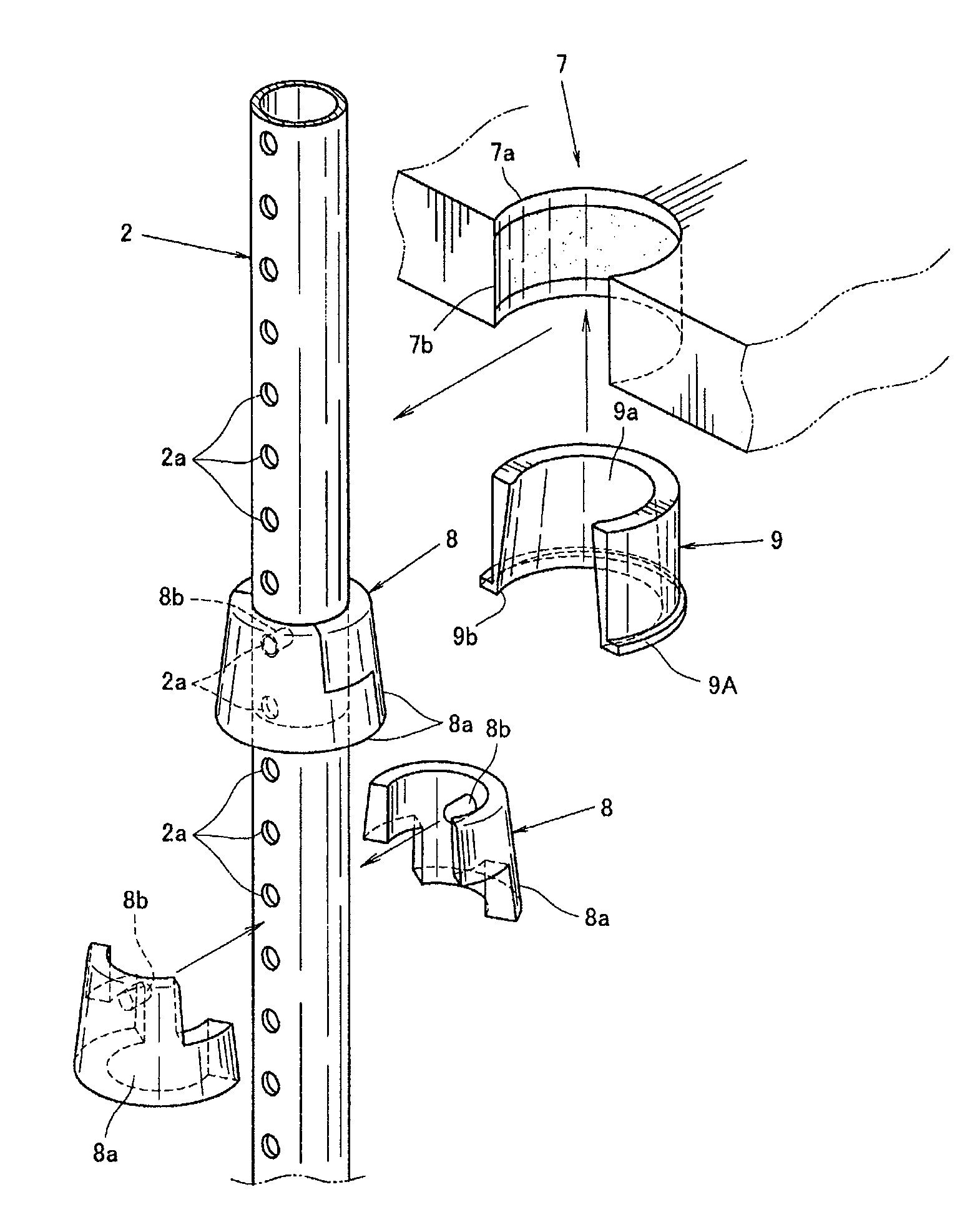
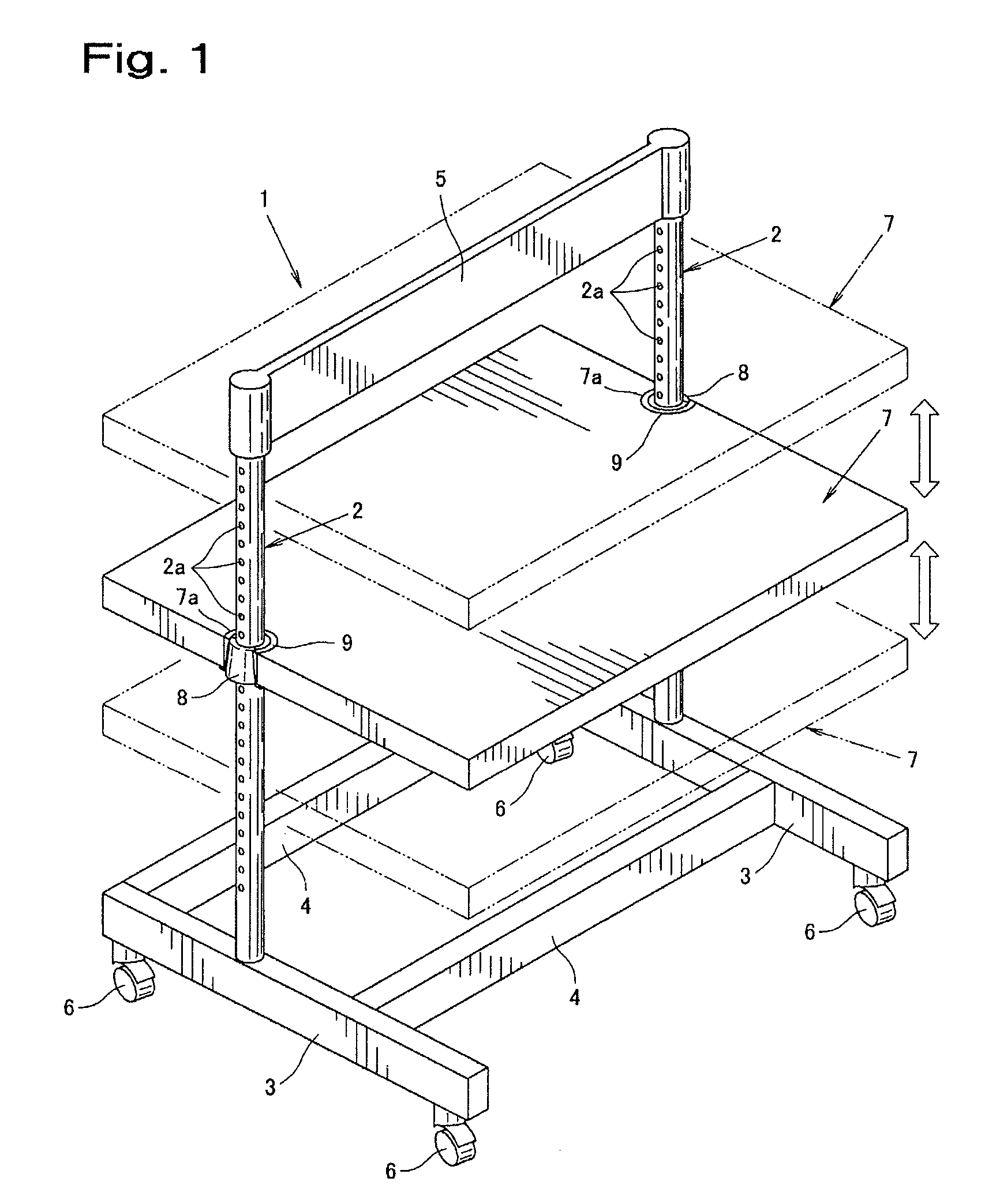
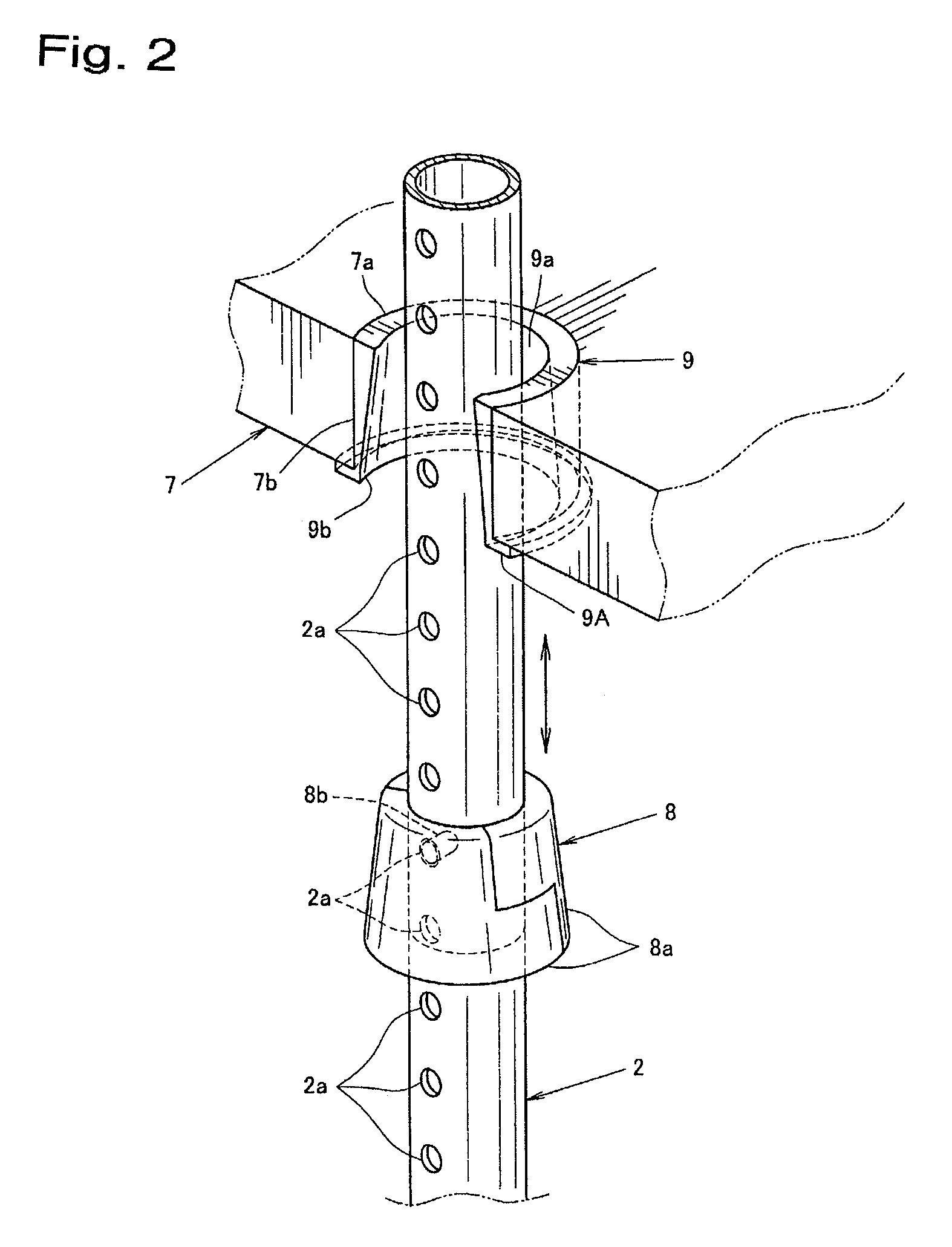
[0094]FIG. 1 and FIG. 2 show an assembly structure of the first embodiment, in which circular trapezoidal insertion members 8, 8 as seen from the side attached to the outside of posts 2, 2 for composing a structure 1 are fitted to C-shaped receiving members 9, 9 as seen from the plane attached to both side edges of the shelf-like structural body 7 from beneath, and they are assembled without using any tool. In the embodiment, the insertion member 8 and receiving member 9 are made of same material, but they may be also made of different materials.

[0095]The hollow posts 2, 2 for composing the structure 1 are erect upright toward the immediately upward direction to the center of the upside of the right and left frame bodies 3, 3.

[0096]At both outer sides of the posts 2, 2, concave holes 2a, for stopping protrusions 8b, 8b formed in the insertion member 8 described later are disposed at specific equal intervals in the length direction along the outside of the hollow post 2 formed in a r...

embodiment 2

[0155]FIG. 22 shows an assembly structure of second embodiment, in which insertion members 8B . . . fitted to a pair of right and left panels 2B, 2B for composing the structure 1 are inserted and fixed in receiving members 9B . . . provided at both edges of shelves 3B . . . for composing, for example, shelf plate, bottom plate or top plate, so as to be assembled without using any tool. In the embodiment, the insertion member 8B and receiving member 9B are made of same material, but may be also made of different materials.

[0156]The structure 1 is composed of two flat panels 2B, 2B which are set up vertically in the immediately upward direction across lateral gap corresponding to the overall length of the shelf 3B, in which insertion members 8B . . . attached to the upper end opposite faces and lower end opposite faces of panels 2B, 2B are fitted and fixed to the receiving members 9B fitted to both edges of the bottom plate shelf 3B and top plate shelf 3B from beneath. Both edges of m...


PUM


Abstract

An assembling structure, wherein an insert member is fixed to the outer surface of a column at a specified position, a receiving member is fixed to a support hole formed at the edge part of a structure beforehand, the portion of the column positioned above a position where the insert member is fixed is inserted, from a horizontal direction, into the receiving hole of the receiving member fitted to the edge part of the structure, and the insert member fitted to the outer surface of the column is fitted, from the lower side, to the receiving hole of the receiving member fitted to the support hole of the structure to assemble them integrally with each other. Or the insert member fitted to a panel or a column is fitted, from the lower side, to the receiving hole of the receiving member fitted to a shelf part to lock locking parts of approximately L-shape in plan view formed on the insert member to locking grooves of approximately L-shape in plan view formed in the receiving member so that the tapered surfaces of the insert member and the receiving member can be fixedly press-fitted against each other.

Description

TECHNICAL FIELD[0001]The invention relates to an assembly structure used in assembling of outdoor structure such as shelf, rack, table, or box.BACKGROUND ART[0002]In a conventional assembly structure, for example, a sleeve is attached to a an upright erect post outside, a collar is fitted to the sleeve attached to the post outside from the side of the post, and both ends of a holder provided at a corner of a shelf plate is extended laterally by resisting the elasticity. Further, both end bumps of the holder are fitted into the recesses formed at the collar lateral side from the side of the collar and are engaged with the both lateral recesses of the collar, and the holder is mounted and assembled on the protrusion protruding to the lower end side of the collar, and the assembly type shelf of patent document 1 is formed.[0003]However, when attaching or detaching the holder on the collar lateral side, the both ends of the holder are extended laterally by resisting the elasticity, but ...

Claims


Application Information

Patent Timeline
Patent Type & Authority Patents(United States)
IPC IPC(8): H01R13/502
CPCA47B47/047A47B57/265F16B2/14F16B3/06F16B9/023F16B12/20F16B12/46F16B17/00F16B9/056F16B2200/503F16B9/054F16B9/052
Inventor TATEMATSU, SHUNJI
Owner FONTAGE
Why Eureka
Try Eureka