
Thread clamp for a rapier head

Inactive Publication Date: 2009-06-09
SULTEX AG
View PDF49 Cites 6 Cited by
  • Summary
  • Abstract
  • Description
  • Claims
  • Application Information

AI Technical Summary

Benefits of technology

[0005]An object of the present invention is to make available a thread clamp for a rapier head of a rapier weaving machine and a rapier head with a thread clamp of this kind as well as a rapier weaving machine with a thread clamp of this kind or with a rapier head of this kind, which require less electrical energy in comparison with the above-described prior art in order to keep the thread clamp open or closed.
[0011]In a further advantageous variant embodiment the thread clamp can in addition be actuated mechanically and / or pneumatically. The thread clamp can thereby for example be opened and closed mechanically and / or pneumatically outside the shed, which reduces the electrical energy consumption and the heating associated therewith.
[0013]The thread clamp in accordance with the invention and the rapier head in accordance with the invention as well as the rapier weaving machine in accordance with the invention have the advantage that the actuator of the thread clamp requires no power either in the closed position or also in the open position of the thread clamp, since the armature is in each case in a rest position which corresponds to the closed or open state of the thread clamp respectively, in which it is held firmly by the holding means. Current is required only for opening and closing of the thread clamp. The total power consumption of the thread clamp is thereby reduced and the actuator can be made smaller and lighter in comparison with actuators of conventional thread clamps without leading to an undesirable warming up of the electromagnet and the other current carrying parts. In addition it is possible in certain phases of the weaving cycle, e.g. when the rapier head is located outside the shed, to actuate the actuator mechanically or pneumatically, which further reduces the heating up of the actuator.

Problems solved by technology

The disadvantage of this arrangement is that the electromagnet must be supplied with power in order to keep the thread clamp open, which can lead to an undesirable heating up of the electromagnet and of the other current carrying parts.
The electrical energy consumption of this thread clamp is therefore comparatively high, even if the opening times of the thread clamp are short in relation to the entire weft insertion cycle.

Method used


Image

  • Thread clamp for a rapier head
  • Thread clamp for a rapier head
  • Thread clamp for a rapier head

Examples


Embodiment Construction

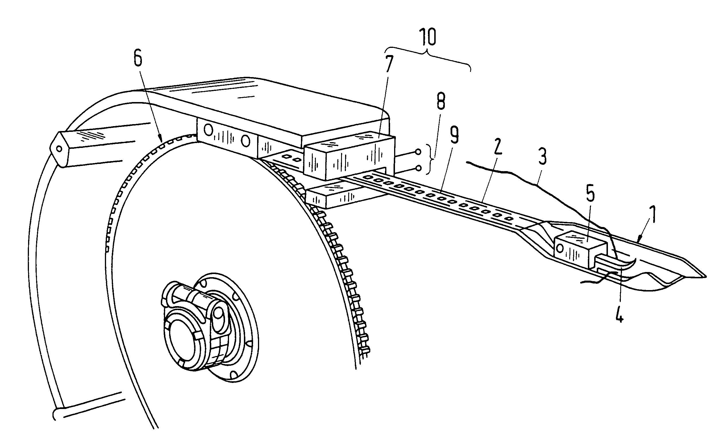
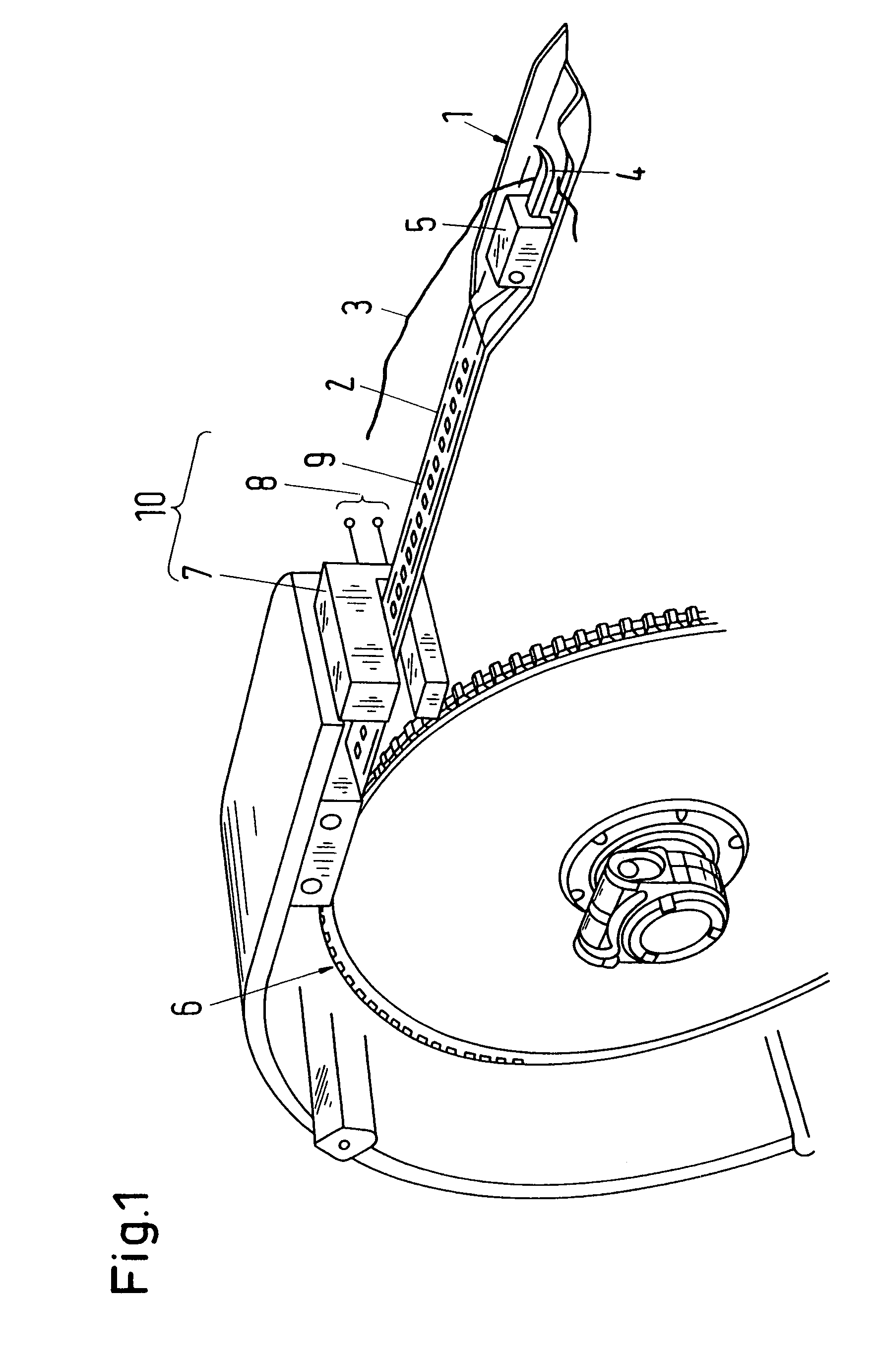
[0019]FIG. 1 shows a schematic illustration of a rapier head 1 and of a band drive with an exemplary embodiment of a thread clamp in accordance with the present invention in a perspective view. The rapier head 1 is connected to a band 2 which is displaceable in the longitudinal direction and which can be moved forwards and backwards by a band drive 6. The band drive 6 includes for example, as shown in FIG. 1, a drive wheel which is provided with teeth at its periphery which engage in cut-outs of the band2. The band guides for guiding the band 2 in the longitudinal direction have been omitted from FIG. 1 for the sake of clarity. If the band is made flexible, it can be led around the drive wheel, as shown in FIG. 1.

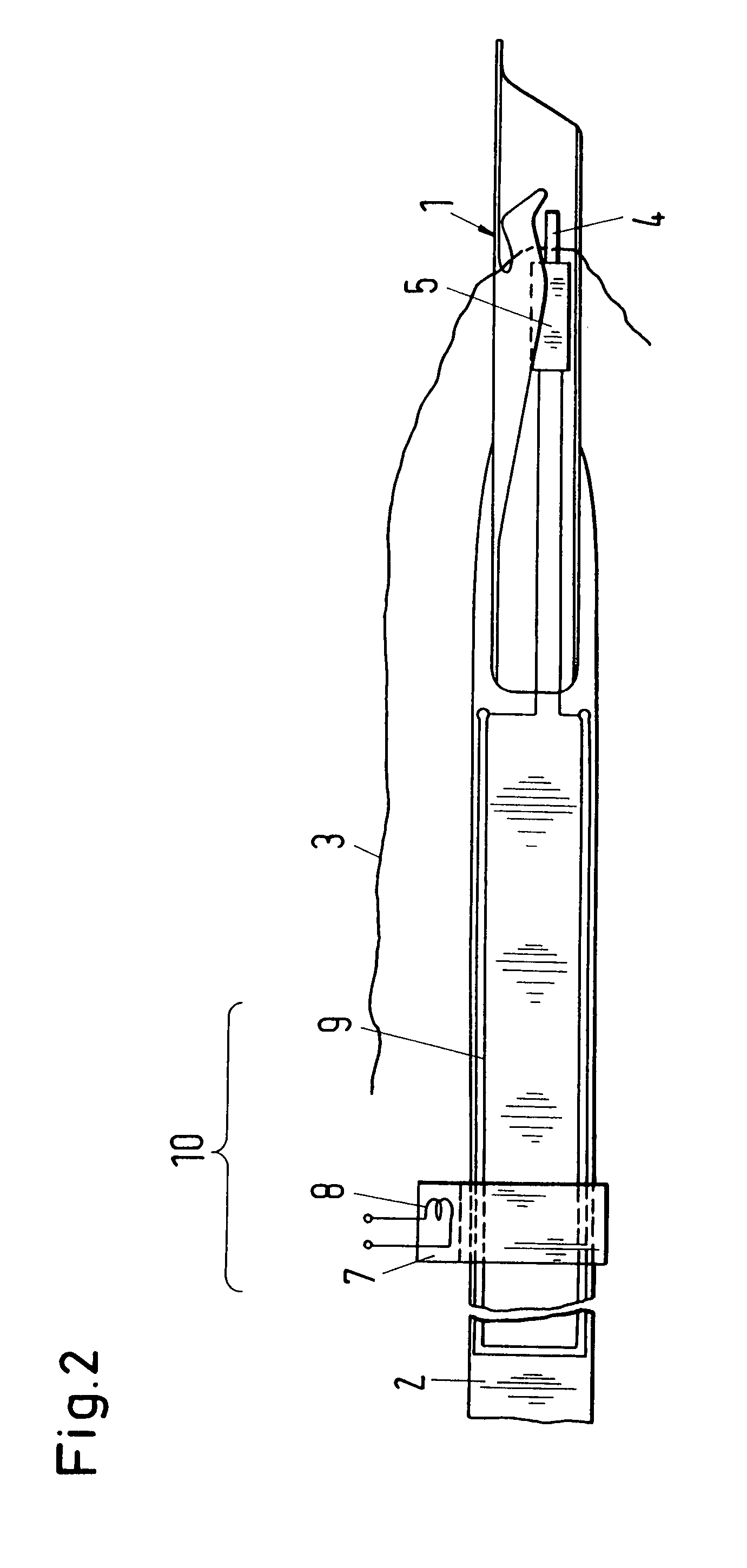
[0020]The thread clamp which, as is shown in FIG. 1, can be arranged in the rapier head 1 contains in the exemplary embodiment a clamping part 4 for firmly clamping a weft thread 3 and an actuator 5 for moving the clamping part 4. For controlling the actuator 5 the latter c...


PUM


Abstract

A thread clamp for a rapier head (1) is presented which contains a clamping part (4) for firmly clamping a weft thread (3) and an actuator (5) for moving the clamping part (4). The actuator (5) includes a ferromagnetic core (12), an armature (11) and at least one winding (13) which is arranged on the core or armature in order to produce a magnetic field in the latter and to move the armature and the clamping part, which is operatively connected to the latter, with the core (12) having two limbs (12.1, 12.2) between which the armature (11) is movably arranged, and with each limb being provided with a permanent magnet (14.1, 14.2) in order to hold the armature at one of the two rest positions in the current-free state of the winding.

Description

CROSS-REFERENCE TO RELATED APPLICATIONS[0001]This application claims the priority of European Patent Application No. 06115598.2, dated Jun. 16, 2006, the disclosure of which is incorporated herein by reference.BACKGROUND OF THE INVENTION[0002]The invention relates to a thread clamp for a rapier head and to a rapier head having a thread clamp of this kind as well as to a rapier weaving machine with a thread clamp of this kind or with a rapier of this kind.[0003]In rapier weaving machines the weft thread is inserted into a shed by means of an inserting rapier, which is mounted on a bar or on a flexible band and is taken over at a transfer point in the central part of the shed by a receiving rapier and further forwarded. The inserting rapier has the task of reliably gripping the presented weft thread, of inserting the latter into the shed and of guiding it precisely to the receiving rapier. Each rapier includes a rapier head with a thread clamp in order to be able to firmly clamp the w...

Claims


Application Information

Patent Timeline
IPC IPC(8): D03D47/23D03D47/27D03D47/28D03D23/00
CPCD03D47/23D03D47/276
Inventor KLAUI, ERICHBACHOFEN, MARIUSMARKWARD, DIETMAR
Owner SULTEX AG
Learn More